SERVICE BULLETIN
V.19
DATE:
7 July
80
Rei
ssued
BULLETIN
NUMBER:
95
MODEL:
All
SUBJECT:
Domesti
c
Hot
Water
Heaters
PRINCIPLE
The
heater
is
connected in series with the engine's freshwater
circuit.
This
allows full water
flow
for
maximum
heat transfer to the heater.
The
series
installation
also avoids several potential
pitfalls
of
installations
in
which
the heater
is
in parallel with
either
the engine's by-pass or
its
internal
freshwater
circuit.
The
only potential disadvantage of a series
installation
is
flow
restriction
due
either
to a
restrictive
heater design, a"large engine water
flow
(such
as
models
W58, W80,
W120),
or a combination of both.
Installation
The
shorter the length of piping to
and
from
the heater, the
better.
The
elevation of the heater should assure
that
the top of
its
internal coil
is
no
higher than the engine pressure cap.
If
the heater
must
be
higher than
this
at
any
heel
angle,
then
the optional
remote
fill
tank
must
be
installed
to
be
the highest point of the
circuit.
Piping
between
the engine
and
heater should
rise
continuously
from
the heater
to the engine
so
that
trapped
air
will
rise
automatically
from
the heater to
the engine.
If
trapped
air
can
rise
to the heater, then a petcock or other
convenient
method
of bleeding
that
air
is
a necessity.
Study
the attached sketches. A convenient place to interrupt the engine cool-
ing
circuit
is
between
the thermostat
housing
outlet
and
the exhaust manifold
inlet.
This
is
also the hottest water available.
CAUTION:
While
most
owners
want
the
hottest
water available,
it
is
possible for scalding water or
even
steam
to
come
from
the faucets.
Since the heater
is
in series with the engine cooling water,
any
other
conven-
ient
point of the
circuit
can
also
be
interrupted for heater
installation.
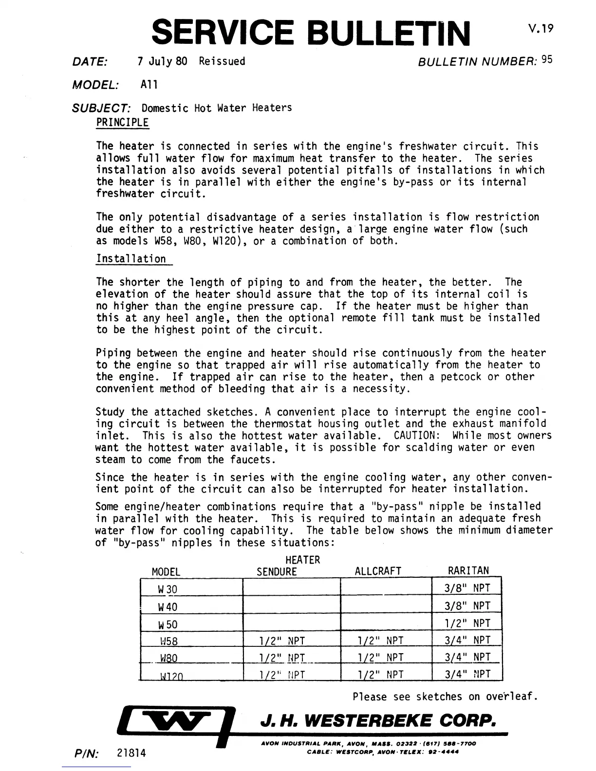
Some
engine/heater combinations require
that
a "by-pass" nipple
be
installed
in parallel with the heater.
This
is
required to maintain
an
adequate fresh
water
flow
for cooling capability.
The
table
below
shows
the
minimum
diameter
of
"by-pass" nipples in these
situations:
MODEL
W30
f---
W40
W
50
H58
r---
HaQ
J..J.l?O
PIN: 21814
HEATER
SENDURE
1/2"
NPT
1/2"IiP.L_
1/2';
r"lPr
ALLCRAFT
RARITAN
3/8"
NPT
3/8"
NPT
1/2"
NPT
1/2"
NPT
3{4"
NPT
1/2"
NPT
3/..1:.NPT
1/2"
NPT
3/4"
NPT
Please see sketches
on
overleaf.
J. H. WESTERBEKE CORP.
AIION
INDUSTRIAL
PARK,
AIION,
If
ASS_ 0:1:1:1:1-
(.f71
5
••
-7700
CA.LE:
WESTCORP,
AIION-
TELEX:
.:1-4444
 Loading...

