THE ENGINE
A
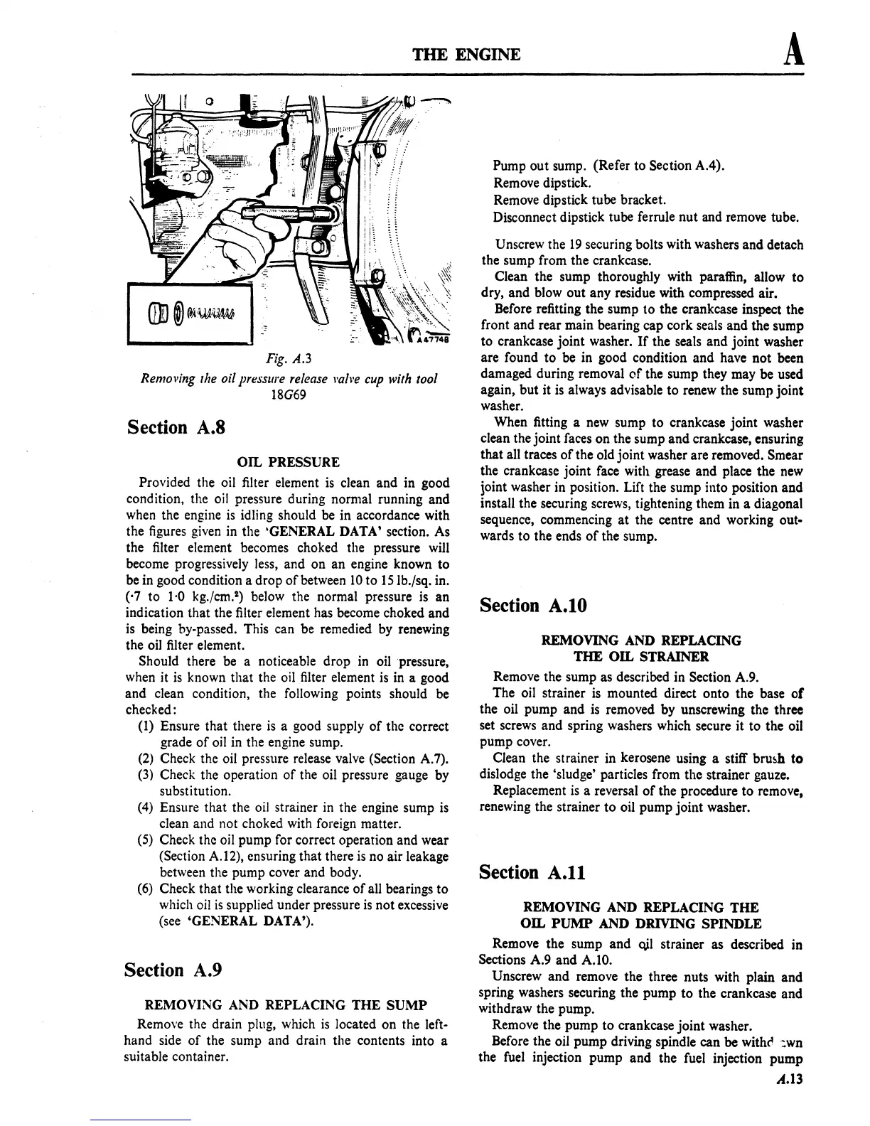
Fig.
A.3
Removing
lire
oil pressure
release
I'ail'e
cup
with
tool
18G69
Section
A.8
OIL
PRESSURE
Provided the oil filter element
is
clean and in good
condition. the
oil
pressure during normal running and
when the engine
is
idling should be in accordance with
the figures given
in
the 'GENERAL DATA' section. As
the filter element becomes choked the pressure will
become progressively less, and on an engine known to
be in good condition a drop
of
between
10
to 15Ib./sq. in.
(,7 to
1·0 kg,fcm.') below the normal pressure
is
an
indication that the filter element has become choked and
is
being by-passed. This can be remedied by renewing
the oil filter element.
Should there be a noticeable drop in oil pressure,
when it
is
known that the oil filter element
is
in a good
and clean condition. the following points should
be
checked:
(I) Ensure that there
is
a good supply
of
the correct
grade
of
oil in the engine sump.
(2)
Check the oil pressure release valve (Section A.7).
(3)
Check the operation
of
the oil pressure gauge by
substitution.
(4)
Ensure that the
oil
strainer in the engine sump
is
clean and not choked with foreign matter.
(5)
Check the oil pump for correct operation and wear
(Section A.12), ensuring that there
is
no air leakage
between the pump cover and body.
(6)
Check that the working clearance
of
aU
bearings to
which oil
is
supplied under pressure
is
not excessive
(see 'GENERAL DATA').
Section
A.9
REMOVING AND REPLACING
THE
SUMP
Remove the drain plug, which
is
located on the left-
hand side
of
the sump and drain the contents into a
suitable container.
Pump out sump. (Refer to Section A.4).
Remove dipstick.
Remove dipstick tube bracket.
Disconnect dipstick tube ferrule nut and remove tube.
Unscrew the
19
securing bolts with washers and detach
the sump from the crankcase.
Clean the sump thoroughly with paraffin, allow to
dry, and
blowout
any residue with compressed air.
Before refitting the sump to the crankcase inspect the
front and rear main bearing cap cork seals and the sump
to crankcase joint washer.
If
the seals and joint washer
are found to be in good condition and have not been
damaged during removal
of
the sump they may be used
again, but it
is
always advisable to renew the sump joint
washer.
When fitting a
new
sump to crankcase joint washer
clean the joint faces on the sump and crankcase, ensuring
that all traces
of
the old joint washer are removed. Smear
the crankcase joint face with grease and place the new
joint washer in position.
Lift
the sump into position and
install the securing screws, tightening them in a diagonal
sequence, commencing
at
the centre and working out-
wards to the ends
of
the sump.
Section
A.IO
REMOVING AND REPLACING
THE
OIL
STRAINER
Remove the sump as described in
Section A.9.
The oil strainer
is
mounted direct onto the base
of
the oil pump and
is
removed by unscrewing the three
set screws and spring washers which secure it to the oil
pump cover.
Clean the strainer in kerosene using a stiff
bru~h
to
dislodge the 'sludge' particles from the strainer gauze.
Replacement
is
a reversal
of
the procedure to remove,
renewing the strainer to oil pump joint washer.
Section
A.II
REMOVING AND REPLACING
THE
OIL
PUMP
AND DRIVING SPINDLE
Remove the sump and
oJl
strainer as described in
Sections A.9 and
A.tO.
Unscrew and remove the three nuts with plain and
spring washers securing the pump to the crankcase and
withdraw the pump.
Remove the pump to crankcase joint washer.
Before the oil pump driving spindle can be
withe'
:wn
the fuel injection pump and the fuel injection pump
A.13
 Loading...

