A
THE ENGINE
Fig.
A.4
The lobe
clea/'a1lce
should not exceed
·006
in.
(·152 mm.)
when
the oil pump rotors are
in
the posi-
tions
illustrated
driving spindle must be removed as described in Sections
D.l2
and A.33.
Replacement is a reversal
of
the foregoing procedure,
using a new oil pump to crankcase joint washer.
Section
A.12
DISMANTLING AND REASSEMBLING
THE
OIL
PUMP
Unscrew the two securing screws and carefully with·
draw the cover, which
is
located on the base
of
the oil
pump body by two dowels.
Withdraw the outer rotor, and the inner rotor complete
with oil pump shaft, from the pump body.
Thoroughly clean all parts inkeFosine and inspect them
for wear. The rotor end-float and lobe clearances should
be checked as follows:
(1)
Install the rotors in the pump body, place a
straight-edge across the joint face
of
the pump
body, and measure the clearance between the
top
face
of
the rotors and the under side
of
the
straight-edge. The clearance should
not
exceed
·005
in. (·127 mm.).
In
cases where the clearance
is
excessive this may be remedied by removing
the two cover locating dowels and carefully
lapping the joint face
of
the pump body.
(2)
Check the diametrical clearance between the outer
rotor and the rotor pocket in the pump body.
If
this exceeds
·010
in. (·254 mm.) and cannot be
remedied by the renewal
of
either the pump body
or
the rotors, then the pump assembly should be
renewed.
(3) With the rotors installed in the pump body
measure the clearance between the rotor lobes
when they are in the positions shown in Fig. A.4.
If
the clearance
is
in excess
of
·006
in. (·152 mm.)
the rotors must be renewed.
Reassembly
is
a reversal
of
the dismantling procedure,
noting the following points:
A.l4
(1) Lubricate all parts with clean engine oil.
(2)
Ensure that the outer
rotor
is installed in the
pump body with
its chamfered end
at
the driving
end
of
the rotor pocket in the pump body.
(3)
After reassembling check the pump for freedom
of
action.
Section A.13
REMOVING AND REPLACING
THE
BIG-END BEARINGS
Remove the sump, oil strainer, and oil pump (Sections
A.9, A.lO, and
A.Il).
Unlock and remove the big-end bearing cap bolts;
withdraw the bearing caps; detach the connecting rods
from the crankshaft and extract the bearing liners.
As the bearings are
of
the shimless type,
it
is essential
that
no attempt be made
to
adjust them. Worn bearings
should always be renewed.
The bearing liners are located in their housings by a
small tag
on
one side
of
each liner engaging a correspond-
ing groove in the connecting rod
and
bearing cap.
It
should be noted
that
the bearings are fitted so
that
the
tags are on the same joint edge
of
the bearing housing,
although
on
opposite corners.
Connecting rods and bearing caps are mated pairs, and
a bearing cap must only be refitted
to
the connecting rod
from which
it
was originally taken.
To
assist when
reassembling, both the connecting rod
and
cap are
stamped with the cylinder number
to
which
it
is fitted,
as shown in Fig. A.6. Bearing liners have
no
such mark-
ings, and when used liners are
to
be refitted they should
be suitably marked with the position in the connecting
rod-that
is, rod
half
or
cap
half-and
the connecting
rod number.
A punch should not be used
to
mark
the liners.
Replacement is a reversal
of
the foregoing procedure.
lubricating the crankpins and bearing liners liberally with
clean engine oil and fitting new bearing cap bolt lock
washers. Tighten the bearing cap bolts
to
the torque
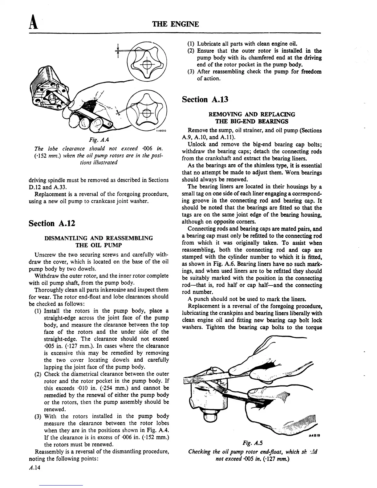
Fig.
A.5
Checking the oil pump rotor
end-JIoat,
which
sir
::!d
not exceed ·005 in. (·127 mm.)
 Loading...

