THE ENGINE
A
c
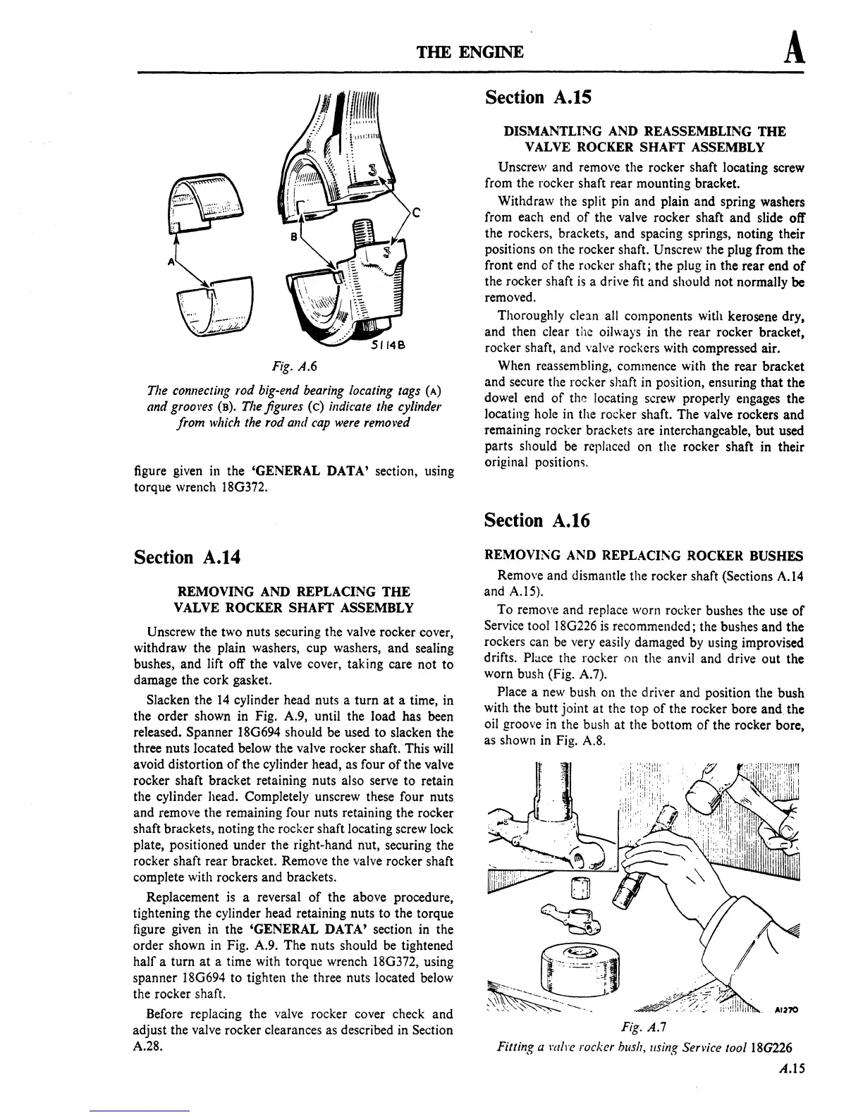
Fig.
A.6
The
connecting rod big-end
bearing
locating tags
(A)
and grool'es
(B).
The
figures (c)
indicate
the cylinder
from
which
the rod and
cap
were
remol'ed
figure given
in
the 'GENERAL DATA' section, using
torque wrench
ISG372.
Section A.14
REMOVING AND REPLACING
THE
VALVE ROCKER SHAFT ASSEMBLY
Unscrew the two nuts securing the valve rocker cover,
withdraw the plain washers, cup washers, and sealing
bushes, and lift off the valve cover, taking care not to
damage the cork gasket.
Slacken the
14
cylinder head nuts a turn
at
a time, in
the order shown in Fig. A.9, until the load has been
released. Spanner
ISG694 should be used to slacken the
three nuts located below the valve rocker shaft.
This
wiII
avoid distortion
of
the cylinder head, as four
of
the valve
rocker shaft bracket retaining nuts also serve to retain
the cylinder head. Completely unscrew these four nuts
and remove the remaining four nuts retaining the rocker
shaft brackets, noting the rocker shaft locating screw lock
plate, positioned under the right-hand nut, securing the
rocker shaft rear bracket. Remove the valve rocker shaft
complete with rockers and brackets.
Replacement
is
a reversal
of
the above procedure,
tightening the cylinder head retaining nuts to the torque
figure given in the 'GENERAL DATA' section in the
order shown in Fig. A.9. The nuts should
be
tightened
half a turn
at
a time with torque wrench ISG372, using
spanner
lSG694 to tighten the three nuts located below
the rocker shaft.
Before replacing the valve rocker cover check and
adjust the valve rocker clearances as described in Section
A.2S.
Section A.IS
DISMANTLING AND REASSEMBLING
THE
VALVE ROCKER SHAFT ASSEMBLY
Unscrew and remove the rocker shaft locating screw
from the rocker shaft rear mounting bracket.
Withdraw the split pin and plain and spring washers
from each end
of
the valve rocker shaft and slide off
the rockers, brackets, and spacing springs, noting their
positions on the rocker shaft. Unscrew the plug from the
front end
of
the rocker shaft; the plug in the rear end
of
the rocker shaft
is
a drive fit and should not normally
be
removed.
Thoroughly
clean all components with kerosene dry.
and then clear the oil
ways
in the rear rocker bracket.
rocker shaft, and
valve rockers with compressed air.
When reassembling, commence with the rear bracket
and secure the rocker shaft in position, ensuring that the
dowel end
of
the locating screw properly engages the
locating hole in the rocker shaft. The valve rockers and
remaining rocker brackets are interchangeable,
but
used
parts should be replaced on the rocker shaft in their
original
position~.
Section A.16
REMOVING AND REPLACI!\G ROCKER BUSHES
Remove and dismantle the rocker shaft (Sections
A.14
and A.15).
To remove and replace worn rocker bushes the use
of
Service tool lSG226
is
recommended; the bushes and the
rockers can
be
very easily damaged by using improvised
drifts. Place the rocker on the anvil and drive out the
worn bush (Fig. A.7).
Place a
new
bush on the driver and position the bush
with the butt joint at the top
of
the rocker bore
and
the
oil groove in the bush at the bottom
of
the rocker bore,
as shown in Fig.
A.S.
Fig.
A.7
Fitting a
mire
rock.er
bliSh,
/Ising
SeTl'ice
toollSG226
A.15
 Loading...

