A
THE ENGINE
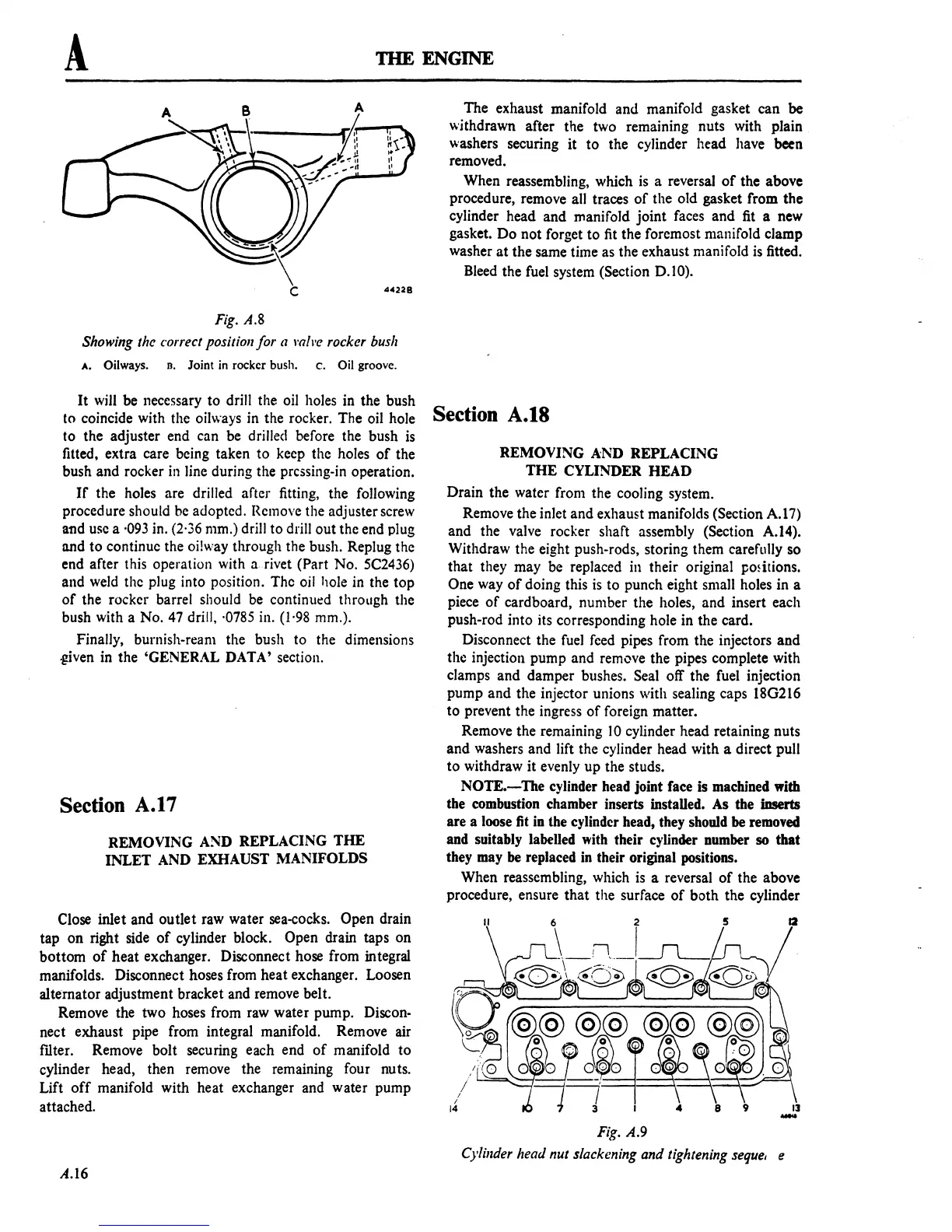
Fig.
A.8
Showing
the correct position for a mh'e rocker bush
A. Oilways.
n.
Joint
in
rockcr bush. c.
Oil
groovc.
It
will be necessary to drill the oil holes in the bush
to coincide with the oilways in the rocker. The oil hole
to the adjuster end can be drilled before the bush
is
fitted, extra care being taken to keep the holes
of
the
bush
and
rocker in line during the pressing-in operation.
If
the holes are drilled after fitting, the following
procedure should be adopted. Remove the adjuster screw
and use a ·093 in. (2'36 mm.) drill to drill out the end plug
and
to
continue the oi!\\'ay through the bush. Replug the
end after this operation with a rivet (Part No. 5C2436)
and weld the plug into position. The oil hole in the
top
of
the rocker barrel should be continul!d through the
bush with a No.
47 drill, ·0785 in. (1·98 mm.).
Finally, burnish-ream the bush to the dimensions
.given in the 'GENERAL DATA' section.
Section A.I7
REMOVING AND REPLACING
THE
INLET
AND EXHAUST MANIFOLDS
Close inlet and outlet raw water sea-cocks. Open drain
tap
on
right side
of
cylinder block. Open drain taps on
bottom
of
heat
exchanger. Disconnect hose from integral
manifolds. Disconnect hoses from heat exchanger. Loosen
alternator adjustment bracket and remove belt.
Remove the two hoses from raw water pump.
Discon-
nect exhaust pipe from integral manifold. Remove air
filter. Remove bolt securing each end
of
manifold
to
cylinder head, then remove the remaining four nuts.
Lift
off
manifold with heat exchanger and water pump
attached.
A.l6
The exhaust manifold and manifold gasket can
be
withdrawn after the two remaining nuts with plain
washers securing it
to
the cylinder head have been
removed.
When reassembling, which
is
a reversal
of
the above
procedure, remove all traces
of
the old gasket from the
cylinder head
and
manifold
joint
faces and fit a new
gasket.
Do
not forget to fit the foremost manifold clamp
washer
at
the same time as the exhaust manifold
is
fitted.
Bleed the fuel system
(Section 0.10).
Section A.IS
REMOVING AND REPLACING
THE
CYLINDER HEAD
Drain the water from the cooling system.
Remove the inlet and exhaust manifolds
(Section A.17)
and the valve rocker shaft assembly (Section A.14).
Withdraw the eight push-rods, storing them carefully so
that
they may be replaced in their original pmitions.
One
way
of
doing this
is
to punch eight small holes in a
piece
of
cardboard, number the holes, and insert each
push-rod into its corresponding hole in the card.
Disconnect the
fuel
feed pipes from the injectors and
the injection pump and remove the pipes complete with
clamps and damper bushes.
Seal off the fuel injection
pump and the injector unions with sealing caps 180216
to prevent the ingress
of
foreign matter.
Remove the remaining
10
cylinder head retaining nuts
and washers and lift the cylinder head with a direct pull
to
withdraw it evenly up the studs.
NOTE.-The
cylinder head joint face is machined with
the combustion chamber inserts installed. As the inserts
are a loose fit
in
the cylinder head, they should
be
removed
and suitably labelled with their cylinder number so that
they may
be
replaced
in
their original positions.
When reassembling, which
is
a reversal
of
the above
procedure, ensure
that
the surface
of
both the cylinder
12
Fig. A.9
Cylillder head nut slackening and tightening seque, e
 Loading...

