A
THE ENGINE
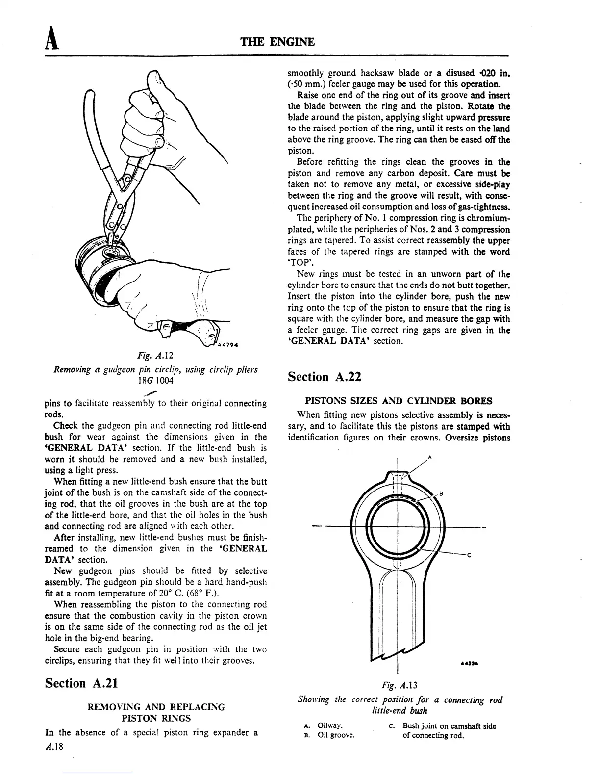
Fig.
A.I2
Removing a gudgeon pin eire/ip,
!Ising
eirclip pliers
18G
1004
_./
pins
to
facilitate reassemhly
to
their original connecting
rods.
Check the gudgeon pin and connecting rod little-end
bush for wear against the dimensions given in the
'GENERAL
DATA'
section.
If
the little-end bush
is
worn it should be removed
and
a new bllSh instalied,
using a light press.
When fitting a new little-end bush ensure that the
butt
joint
of
the bush
is
on
the camshaft side
of
the connect-
ing rod,
that
the oil grooves in the bush are at the
top
of
the little-end bore, and
that
the oil holes in the bush
and
connecting rod are aligned with each other.
After installing, new little-end bushes must be
finish-
reamed
to
the dimemion given in the
'GENERAL
DATA'
section.
New gudgeon pins should be
fItted by selective
assembly. The gudgeon pin should be a hard
hand-push
fit
at
a room temperature
of
20°
C.
(68
0
F.).
When reassembling the piston to the connecting rod
ensure
that
the combustion cavity in the piston erown
is
on
the same side
of
the connecting rod as the oil jet
hole in the big-end bearing.
Secure each gudgeon pin in position with the two
circlips, ensuring that they
fit
well into their grooves.
Section
A.21
REMOVL,\G AND REPLACING
PISTON
RINGS
In
the absence
of
a special piston ring expander a
A.18
smoothly ground hacksaw blade
or
a disused
-020
in.
('50 mm.) feeler gauge may be used for this operation.
Raise one end
of
the ring
out
of
its groove
and
insert
the blade between the ring
and
the piston.
Rotate
the
blade around the piston, applying slight upward pressure
to
the raised portion
of
the ring, until it rests
on
the
land
above the ring groove. The ring can then be eased off the
piston.
Before refitting the rings clean the grooves in the
piston and remove any carbon deposit. Care
must
be
taken not
to
remove any metal,
or
excessive side-play
between the ring and the groove will result, with
conse-
quent increased oil consumption and loss
of
gas-tightness.
The periphery
of
No.1
compression ring is chromium-
plated, while the peripheries
of
Nos. 2
and
3 compression
rings arc tapered.
To
assist correct reassembly the upper
faces
of
the tapered rings are stamped with the word
'TOP'.
New rings must be tested in
an
unworn
part
of
the
cylinder bore to ensure that the
entis
do
not
butt
together.
Insert the piston into the cylinder bore, push the new
ring
onto
the top
of
the piston
to
ensure
that
the ring is
square
with the cylinder bore, and measure the gap with
a feeler gauge. The correct ring gaps are given in the
'GENERAL DATA' section.
Section A.22
PISTONS
SIZES
AND CYLINDER
BORES
When fitting new pistons selective assembly is neces-
sary, and
to
facilitate this the pistons
are
stamped with
identification
figures
on
their crowns. Oversize pistons
Fig. A.13
Sho1l'ing
the correct position
for
a connecting rod
little-end
bush
A. Oilway.
B. Oil groove.
c. Bush joint on camshaft side
of
connecting rod.
 Loading...

