TIlE
ENGINE
A
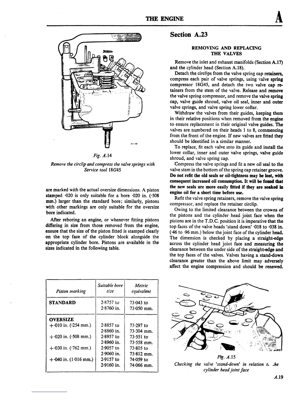
Fig. A.14
Remove the eire/ip and compress
the valve springs with
Service
tool 18G45
are marked with the actual oversize dimensions. A piston
stamped
·020
is only suitable for a bore
·020
in.
(·508
mm.) larger
than
the standard bore; similarly, pistons
with other markings are only suitable for the oversize
bore indicated.
After reboring
an
engine,
or
whenever fitting pistons
differing in size from those removed from the engine,
ensure that the size
of
the piston fitted
is
stamped clearly
on
the top face
of
the cylinder block alongside the
appropriate cylinder bore. Pistons are available in the
sizes indicated in the following table.
Suitable bore
Metric
Piston marking
size
equh'alent
STANDARD
2·R757
to
73·043
to
2·8760
in.
73·050
mm.
OVERSIZE
+'010
in.
(·254
mm.)
2·8857
to
7'3'297
to
2·8860
in.
73·304
mm.
+020
in. ('508 mm.)
2-8957
to
73·551
to
2·8960
in.
73'558
mm.
+·030 in. ('762 mm.)
2·9057
to
73-805
to
2·9060
in.
73·812
mm.
+·040 in. (1'016 mm.)
2·9157
to
74·059
to
2·9160
in.
74·066
mm.
Section
A.23
REMOVING AND REPLACING
THE
VALVES
Remove the inlet and exhaust manifolds (Section
A.17)
and
the cylinder head (Section A.l8).
Detach the circJips from the valve spring cap retainers,
compress each pair
of
valve springs, using valve spring
compressor
18G45,
and
detach the two valve cap
re-
tainers from the stem
of
the valve. Release and remove
the valve spring compressor, and remove the valve spring
cap, valve guide shroud, valve oil seal, inner
and
outer
valve springs,
and
valve spring lower collar.
Withdraw the valves from their guides, keeping them
in their relative positions when removed from the
~ngine
to
ensure replacement in their original valve guides.
The
valves are numbered on their heads I to 8, commencing
from the front
of
the engine.
If
new valves are fitted they
should be identified in a similar manner.
To
replace,
fit
each valve mto its guide and install the
lower collar, inner and outer valve springs, valve guide
shroud, and valve spring cap.
Compress the valve springs and
fit
a new oil seal to the
valve stem in the bottom of-the spring cap retainer groove.
Do not refit the old seals or oil-tightness may
be
lost,
with
consequent increased oil consumption.
It
will
be
food
that
the
new
seals are more easily fitted
if
they are soaked
iD
engine oil for a short time before use.
Refit the valve spring retainers, remove the valve spring
compressor, and replace the retainer circlip.
Owing
to
the limited clearance between the crowns
of
the pistons and the cylinder head joint face when the
pistons are in the T.D.C. position it is imperative
that
the
top faces
of
the valve heads 'stand down'
·018
to
·038
in.
(·46 to
·96
mm.) below the joint face
of
the cylinder head.
The dimension is checked by placing a straight-edge
across the cylinder head
joint
face
and
measuring the
clearance between the under side
of
the straight-edge
and
the top faces
of
the valves. Valves having a stand-down
clearance greater
than
the above limit may adversely
affect the engine compression
and
should be renewed.
i~
Fig.
A.15
Checking the valve 'stand-down'
in
relation t.
~he
cylinder head joint face
A.19
 Loading...

