A
THE ENGINE
A4839
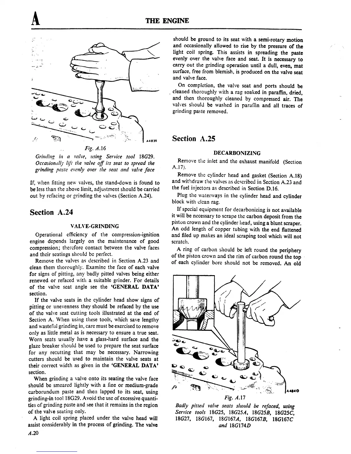
Fig. A.16
Grinding
ill
a
l'(!/re,
using Service .tool
18G29.
Occasionlllly
[{Ii
the l'alve
off
its seat to spread the
grinding
paste cl'£'"ly over the seat and
l'Q!J'e
face
If, when fitting
new
valves, the stand-down
is
found to
be
less
than the above limit, adjustment should be carried
out hy refacing
or
grinding the valves (Section A.24).
Section A.24
v AINE-GRINDING
Operational efficiency
of
the compression-ignition
engine depends largely on the maintenance
of
good
compression; therefore contact between the valve faces
and their seatings should
be
perfect.
Remove the valves
as described
in
Section A.23 and
clean them thoroughly. Examine the face
of
each valve
for signs
of
pitting, any badly pitted valves being either
renewed
or
refaced with a suitable grinder.
For
details
of
the valve scat angle
see
the 'GENERAL DATA'
section.
If
the valve seats in the cylinder head show signs
of
pitting
or
unevenness they should be
ref
aced
by
the use
of
the valve seat cutting tools illustrated
at
the end
of
Section
A.
When using these tools, which save lengthy
and wasteful grinding in, care must be exercised to remove
only as little metal as
is
necessary to ensure a true seat.
Worn seats u5ually have a glass-hard surface and the
glaze breaker should
be
used to prepare the seat surface
for any recutting that may be necessary. Narrowing
cutters should
be
used to maintain the valve seats
at
their correct width as given in the 'GENERAL DATA'
section.
When grinding a valve onto its seating the valve face
should be smeared lightly with a
fine
or
medium-grade
carborundum paste and then lapped to its seat, using
grinding-in too118G29. Avoid the usc
of
excessive quanti-
ties
of
grinding paste and
see
that it remains in the region
of
the valve seating only.
A light coil spring placed under the valve head
will
assist considerably in the process
of
grinding. The valve
04.20
should be ground to its seat with a semi-rotary motion
and occasionally allowed to rise by the pressure
of
the
light coil spring. This assists in spreading the paste
evenly over the valve face and seat.
It
is necessary
to
carry out the grinding operation until a dull, even, mat
surface, free from blemish,
is
produced on the valve seat
and valve face.
On completion, the valve seat and ports should be
. cleaned thoroughly with a rag soaked in paraffin, dried,
and then thoroughly cleaned by compressed air. The
vah'es should be washed
in
paraffin and all traces
of
grinding paste removed.
Section A.25
DECARBONIZING
Remo\'e
the inlet and the exhaust manifold (Section
A.17).
Remove the cylinder head and gasket (Section A.l8)
and withdraw the
valves as
de~cribed
in Section A.23 and
the
fuel
injectors as described
in
Section D.16.
Plug the waterways in the cylinder head and cylinder
block with
dean
rag.
If
special equipment for decarbonizing is not available
it
will
be necessary to scrape thc carbon deposit from the
piston crown and the cylinder head, using a blunt scraper.
An odd length
of
copper tubing with the end flattened
and
filed
up makes an ideal scraping tool which will not
scratch.
A ring
of
carbon should
be
left round the periphery
of
the piston crown and the rim
of
carbon round the top ,
of
each cylinder bore should not be removed.
An
old
10:)
~
Q.:,
~
~
~
6:,)
~--,:~
Fig. A.17
Badly
pitted
vall'e seats should be refaced, using
Senice
tools
18G25,
18G25A, 18G25B, 18G25C,
18G27, 18G167, 18G167A, 18G167B, 18G167C
and
18G174D
 Loading...

