THE ENGINE
A
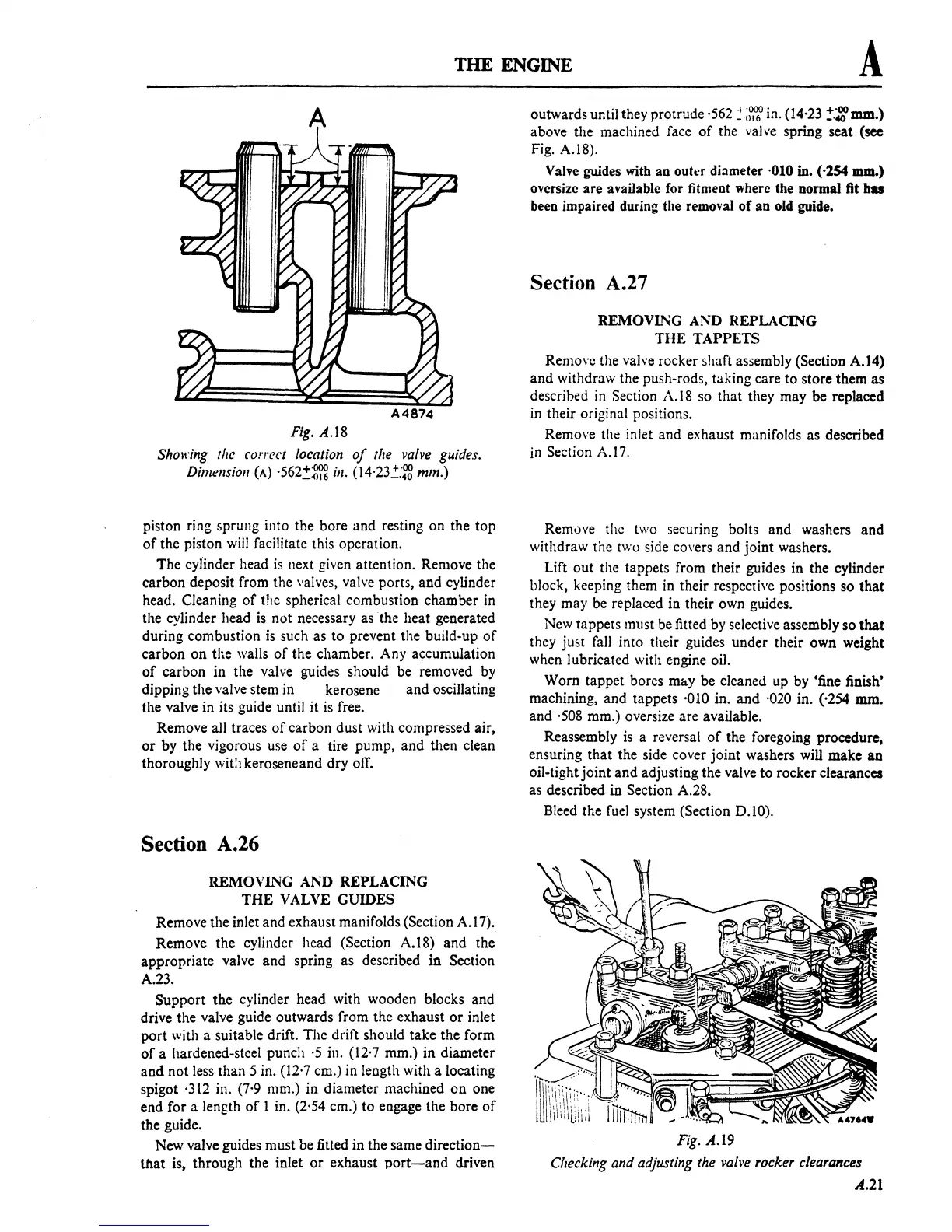
Fig.
A.lS
Showing the correct location
of
the
valve
guides.
Dimension
(A)
'562!:m
ill.
(I4'23"::"~
mm.)
piston ring sprung into the bore and resting
on
the top
of
the piston will facilitate this operation.
The cylinder head
is
next given attention. Remove the
carbon deposit from the valves, valve ports, and cylinder
head. Cleaning
of
the spherical combustion chamber
in
the cylinder head
is
not necessary as the heat generated
during combustion
is
such as to prevent the build-up
of
carbon
on
the walls
of
the chamber. Any accumulation
of
carbon in the valve guides should be removed by
dipping the valve stem in kerosene and oscillating
the valve in its guide until it
is
free.
Remove all traces
of
carbon dust with compressed air,
or
by the vigorous use
of
a tire pump, and then clean
thoroughly with kerosene and dry off.
Section A.26
REMOVL"IG AND REPLACING
THE
VALVE GUIDES
Remove the inlet and exhaust manifolds
(Section A. I 7).
Remove the cylinder head
(Section A.IS) and the
appropriate valve and spring as described
in
Section
A.23.
Support the cylinder head with wooden blocks and
drive the valve guide outwards from the exhaust
or
inlet
port
with a suitable drift. The drift should take the form
of
a hardened-steel punch
·5
in. (12'7 mm.) in diameter
and
not
less than 5 in. (12'7 em.) in length with a locating
spigot
·312 in. (7'9 mm.) in diameter machined
on
one
end for a length
of
I in. (2'54 cm.) to engage the bore
of
the guide.
New valve guides must be fitted in the same
direction-
that
is, through the inlet
or
exhaust
port-and
driven
outwards until they protrude
·562 :
~~
in. (14·23
!.;:mm.)
above the machined face
of
the valve spring seat (see
Fig. A.18).
Valve guides
with
an outer diameter ·010 in. ('254 mm.)
oversize are available for fitment where the normal
fit
bas
been impaired during the removal
of
an old guide.
Section A.27
REMOVING AND REPLACING
THE
TAPPETS
Remove the valve rocker
shan
assembly (Section
A.l4)
and withdraw the push-rods, taking care to store them
as
described
in
Section
A.18
so that they may
be
replaced
in
their original positions.
Remove
the inlet and exhaust manifolds as described
in Section A.17.
Remove the two securing bolts and washers and
withdraw the two side
covers and joint washers.
Lift out the tappets from their guides in the cylinder
block, keeping them
in
their respective positions so
that
they may be replaced in their own guides.
New tappets must
be
fitted by selective assembly so
that
they just fall into their guides under their own weight
when lubricated with engine oil.
Worn tappet bores
mlly be cleaned up by 'fine finish'
machining, and tappets ·010 in. and ·020 in. (·254
mm.
and
·508
mm.) oversize are available.
Reassembly
is
a reversal
of
the foregoing procedure,
ensuring that the side cover joint washers will make
an
oil-tight
joint
and adjusting the valve to rocker clearances
as described in Section A.28.
Bleed the fuel system
(Section 0.10).
Fig.
A.I9
Cbecking and adjusting the vahe rocker clearances
A.21
 Loading...

