A
THE ENGINE
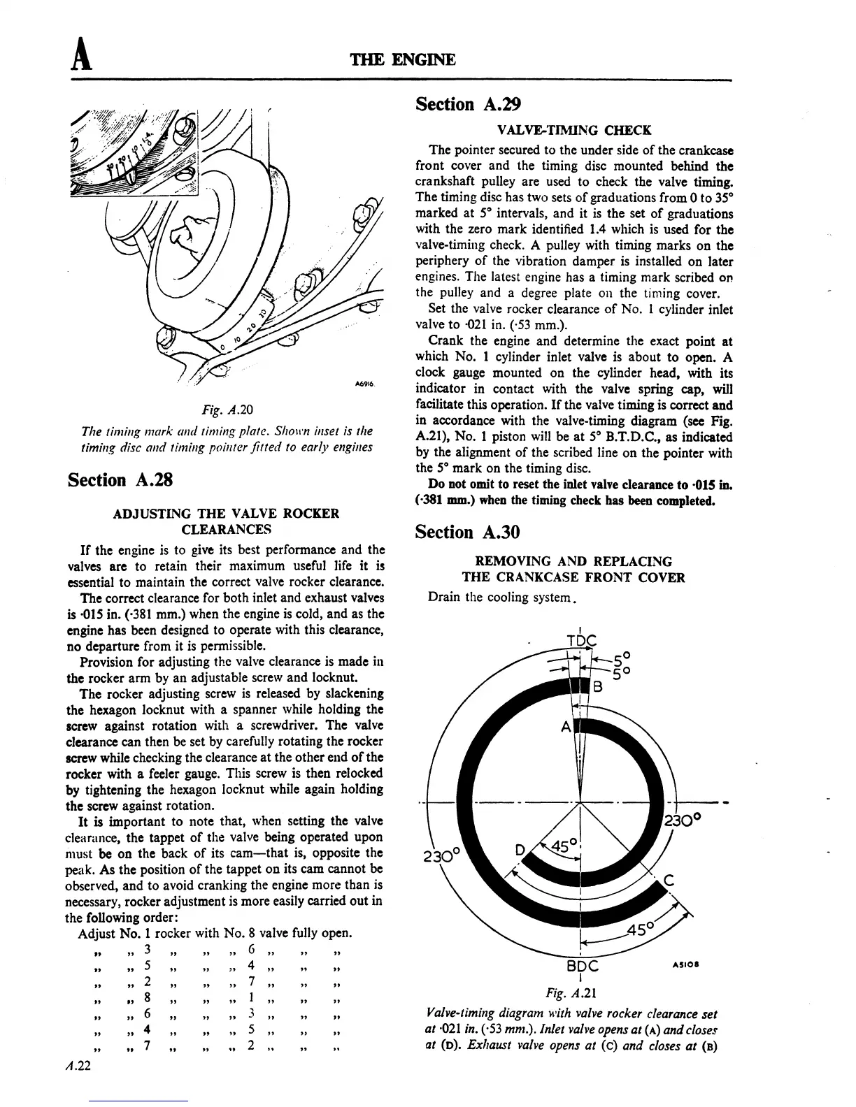
Fig. A.20
The timing mark and timing plate. Sholl'n inset is the
timing disc and timing poill1er fitted to early engilles
Section A.28
ADJUSTING
THE
VALVE ROCKER
CLEARANCES
If
the engine is
to
give its best performance and the
valves
arc to retain their maximum useful life it is
essential
to
maintain the correct valve rocker clearance.
The correct clearance for both inlet and exhaust valves
is
-015
in. (·381 mm.) when the engine
is
cold, and as the
engine has been designed
to
operate with this clearance,
no departure from it is permissible.
Provision for adjusting the valve clearance is made ill
the rocker arm by
an
adjustable screw and locknut.
The
rocker adjusting screw
is
released by slackening
the hexagon locknut with a spanner while holding the
screw
against rotation with a screwdriver. The valve
clearance can then be set by carefully rotating the rocker
screw
while checking the clearance
at
the other end
of
the
rocker with a feeler gauge. This screw is then relocked
by tightening the hexagon locknut while again holding
the screw against rotation.
It
is important
to
note that, when setting the valve
clearance, the tappet
of
the valve being operated upon
must be
on
the back
of
its
cam-that
is, opposite the
peak. As the position
of
the tappet
on
its
cam
cannot be
observed, and
to
avoid cranking the engine more than is
necessary, rocker adjustment
is
more easily carried out in
the following order:
Adjust
No.1
rocker with
No.8
valve fully open.
"
"3,,
""6,,
" "
It
"5,,
"4,,
"
"
"2,,
""7,,
" "
"
.,8"
""1,,
" "
"
,,6
" "
3"
" "
"
"4,,
""5,,
" "
",,7
.,2""
A.22
Section A.29
VALVE-TIMING CHECK
The pointer secured
to
the under side
of
the crankcase
front cover and the timing disc mounted behind the
crankshaft pulley are used
to
check the valve timing.
The timing disc has two sets
of
graduations from 0
to
35°
marked
at
5°
intervals, and it
is
the set
of
graduations
with the zero mark identified
1.4
which
is
used for the
valve-timing check. A pulley with timing marks on the
periphery
of
the vibration damper
is
installed on later
engines. The latest engine has a timing mark scribed on
the pulley and a degree plate 011 the timing cover.
Set the valve rocker clearance
of
No.1
cylinder inlet
valve
to
-021
in. ('53 mm.).
Crank the engine and determine the exact point
at
which No. 1 cylinder inlet valve is about
to
open. A
clock gauge mounted on the cylinder head, with its
indicator in contact with the valve spring cap,
will
facilitate this operation.
If
the valve timing is correct and
in accordance with the valve-timing diagram (sec Fig.
A.21), No. 1 piston will be
at
5°
B.T.D.C
.•
as
indicated
by the alignment
of
the scribed line
on
the pointer with
the
5°
mark on the timing disc.
Do
not omit to reset the inlet valve clearance
to
·015 in.
(,381
IDOl.)
when the timing check bas been completed.
Section A.30
REMOVING AND REPLACING
THE
CRANKCASE
FRONT
COVER
Drain the cooling system.
SDC
I
Fig.
A.21
ASiOI
Valve-timing diagram with valve rocker clearance
set
at
·021
in. (·53
mm.).lnlet
valve opens
at
(A)
and
closes
at
(D).
Exhaust valve opens
at
(c)
and
closes
at
(8)
 Loading...

