THE ENGINE
A
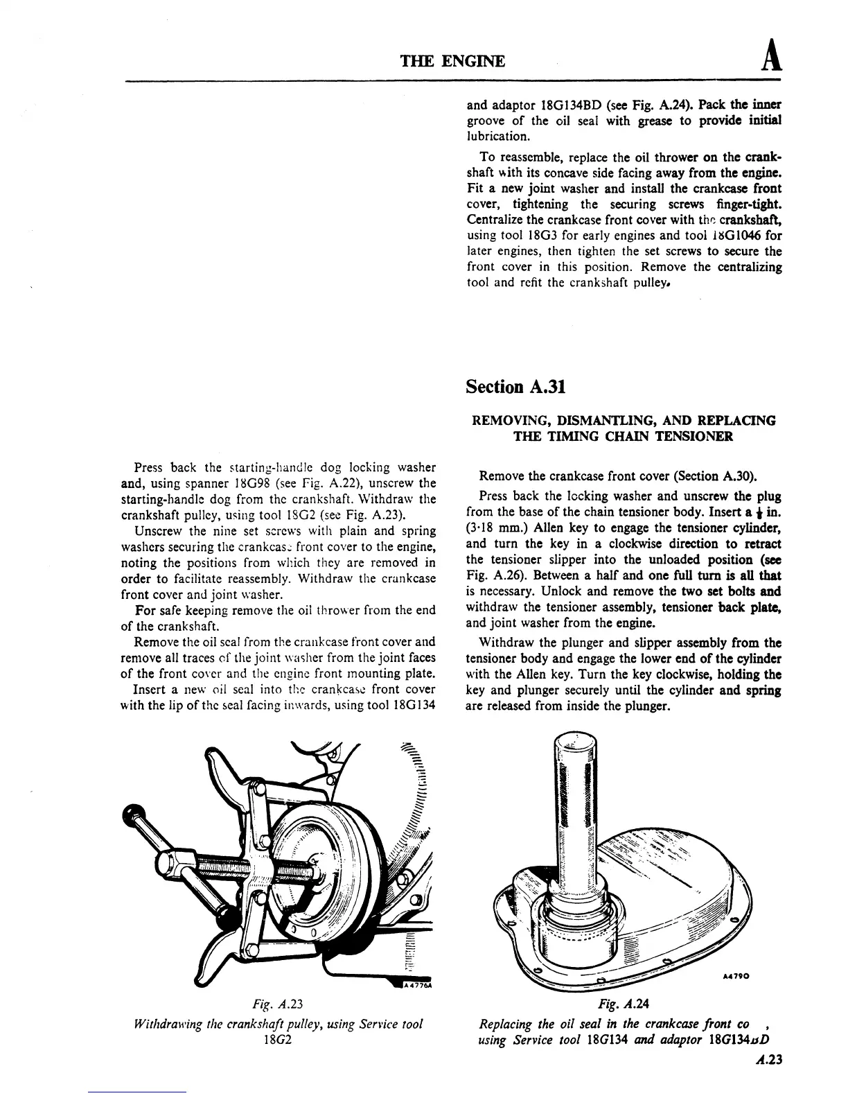
Press back the starting-handle dog locking washer
and, using spanner
18G98
(see Fig. A.22), unscrew the
starting-handle dog from the crankshaft.
Withdraw the
crankshaft pulley,
u!'ing tool 18G2 (see Fig. A.23).
Unscrew the nine set screws with plain and spring
washers securing the
crankcas~
front cover to the engine,
noting the positions from which they are removed in
order to facilitate reassembly. Withdraw the crankcase
front cover and joint washer.
For
safe keeping remove the oil thrower from the end
of
the crankshaft.
Remove the oil seal from the crankcase front cover and
remove all traces
or
the joint washer from the joint faces
of
the front co\'er and the engine front mounting plate.
Insert a
new
oil seal into the
cran~ca,e
front cover
with the lip
of
the
5eal
facing inwards, using tool
18G
134
Fig.
A.23
Withdrawing the crankshaft pulley, using Sen'ice tool
18G2
and adaptor 18Gl34BD (see Fig. A.24). Pack the inner
groove
of
the oil seal with
grease
to
provide initial
lubrication.
To reassemble, replace the oil thrower
on
the crank-
shaft
y,ith its concave side facing away from the engine.
Fit a
new
joint washer and install the crankcase front
cover, tightening the securing screws finger-tight.
Centralize the crankcase front
cover with
thr:
crankshaft,
using tool 18G3 for early engines and tool
HSGI046
for
later engines, then tighten the set screws
to
secure the
front cover in this position. Remove the centralizing
tool and refit the crankshaft pulley.
Section A.31
REMOVING, DISMANTLING, AND REPLACING
THE
TIMING CHAIN TENSIONER
Remove the crankcase front cover (Section A.30).
Press back the locking washer and unscrew the plug
from the base
of
the chain tensioner body. Insert a
..
in.
(3·18 mm.) Allen key to engage the tensioner cylinder,
and turn the key in a clockwise direction
to
retract
the tensioner slipper into the unloaded position (see
Fig. A.26). Between a half and one
fuU
tum
is
aU
that
is
necessary. Unlock and remove the two set bolts
and
withdraw the tensioner assembly, tensioner back plate,
and joint washer from the engine.
Withdraw the plunger and slipper assembly from the
tensioner body and engage the lower end
of
the cylinder
with the Allen
key.
Turn the key clockwise, holding the
key and plunger securely until the cylinder
and
spring
are released from inside the plunger.
Fig.
A.24
Replacing the oil seal
in
the crankcase front
co
,
using Service tool
18G134
and
adaptor 18G134DD
A.23