A
THE ENGINE
Fig.
A.25
Install
the
securing
screws
finger tight
and
centralize
the
crankcase
front
cover
with
the
crankshaft,
using
Service
tool 18G3/or
early
engines
and
tool 18GI046
for
later
engines
Check the bore in the tensioner body for ovality.
If
ovality
is
greater than
·003
in. (·0762 mm.) when measured
on
diameters near the mouth
of
the bore, then the com-
plete chain tensioner should be renewed.
Inspect the slipper head for wear.
If
it is badly worn a
new slipper head and cylinder assembly should be fitted
to the existing body, provided the bore
of
the body is
within the limit given above.
The components should be cleaned thoroughly in clean
petrol,
and
the ·125 in. (3·18 mm.) diameter inlet oil hole
in the spigot
and
the ·040 in.
(I
·02
mm.) outlet oil hole
in the slipper should be cleaned with compressed air
before reassembling.
When the tensioner
is
in operation and the engine
is
running, oil from the lubrication system enters the
spigot on the back face under pressure and lubricates
the bearing surface through a hole in the slipper pad.
The pad
is
held against the chain by the CI)i1 spring.
Should the chain stretch with use, the slipper plunger
rises and the limiting peg, bearing
on
the top
of
the
helical slot, rotates the cylinder until the next recess in the
lower edge
of
the slot comes into line with the limiting peg
and prevents the plunger returning
to
its original position
and allowing the timing chain
to
become slack again.
When reassembling, insert the spring in the plunger
and place the cylinder
on
the other end
of
the spring.
Compress the spring until the cylinder enters the
plunger bore, engaging the helical slot with the peg in
the plunger. Hold the assembly compressed in this
position and engage the Allen key. Turn the cylinder
clockwise until the end
of
the cylinder is below the peg
and the spring
is
held compressed. Withdraw the key and
insert the plunger assembly in the body. Replace the
"'.24
joint washer
and
the back plate and secure the assembly
to the cylinder block.
After refitting the tensioner check the slipper head for
freedom
of
movement
and
ensure
that
it does
not
bind
on
the back plate when
it
is moved
in
the body.
Release the tensioner, by inserting
and
turning
the
Allen
key
in a clockwise direction, until the slipper head
moves forward under spring pressure against the timing
chain.
Do
not attempt to turn the key anti-dockwise
or
force
the sUpper head into the chain by external pressure.
Secure the bolts with the locking plate, replace the
bottom plug,
and
lock with the
tab
washer.
Section A.32
REMOVING AND REPLACING
THE
TIMING
CHAIN
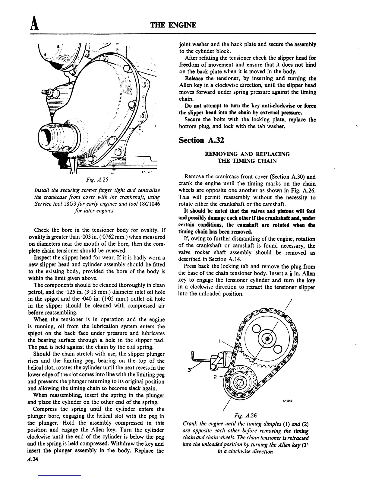
Remove thc crankcase front
,over
(Section A.30) and
crank the
engine until the timing marks
on
the chain
wheels are opposite one another as shown in Fig. A.26.
This will permit reassembly without the necessity
to
rotate either the crankshaft
or
the camshaft.
It
should be
Doted
that the valves and pistons will foul
and possibly damage
each other
if
the crankshaft and, under
certain conditions, the camshaft are rotated when the
timing chain has
been
removed.
If,
owing to further dismantling
of
the engine, rotation
of
the crankshaft
or
camshaft is found necessary, the
valve rocker shaft assembly should be removed as
described in Section
A.14.
Press back the locking
tab
and
remove the plug from
the base
of
the chain tensioner body. Insert a i in. Allen
key
to
engage the tensioner cylinder
and
tum
the
key
in a clockwise direction
to
retract the tensioner slipper
into the unloaded position.
Fig.
A.26
Crank
the
engine
until
the
timing
dimples
(1)
and
(2)
are
opposite
each
other
before
removing
the
timing
chain
and
chain
wheels.
The
c/rain
tensioner
is
retracted
into
the
unloaded
position by
turning
the Allen key (3'
in
a
clockwise
direction
 Loading...

