THE ENGINE
A
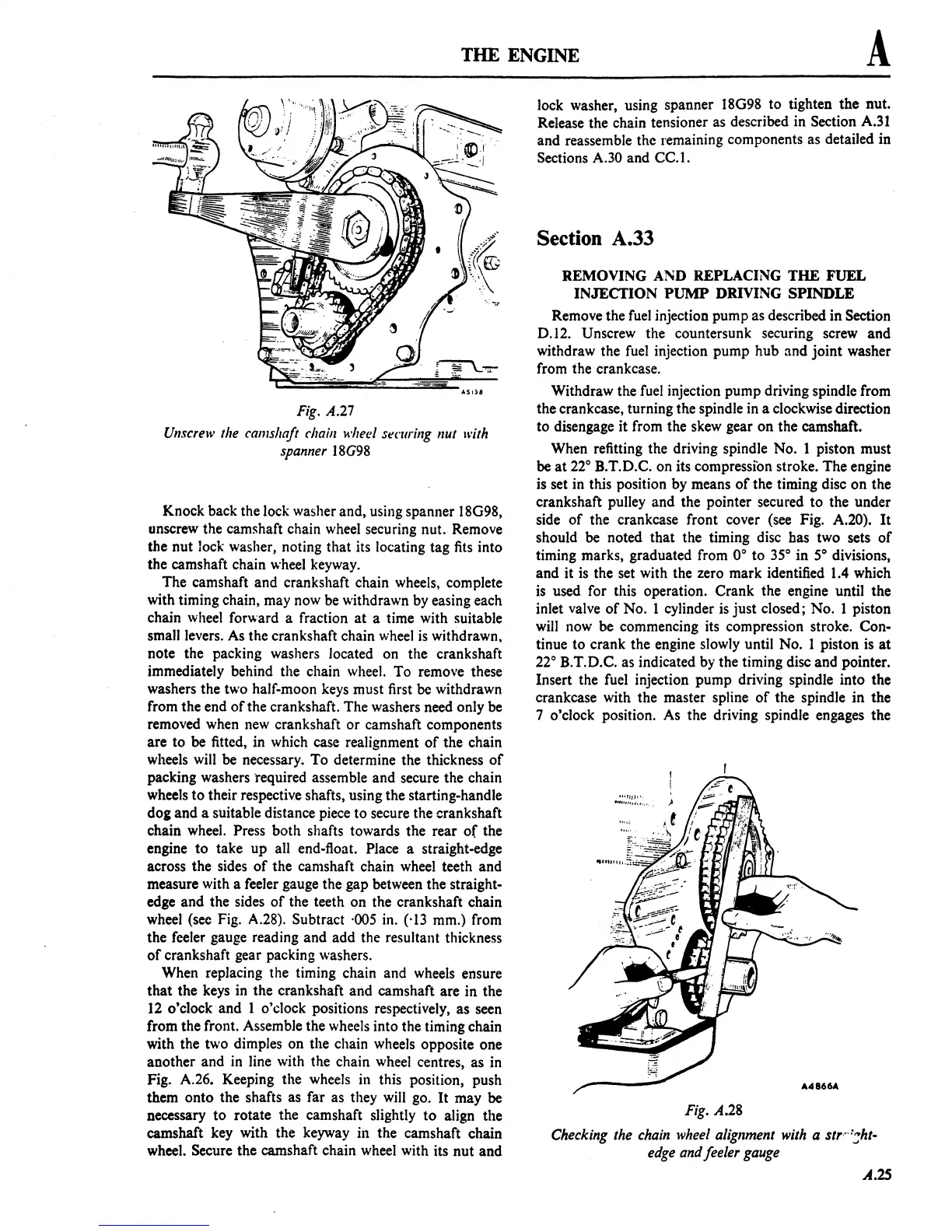
Fig.
A.27
Unscrew
the
camshaft
chain
.....
heel
sl!Cllr;ng
nut
with
spanner
l8G98
Knock back the lock washer and, using spanner l8G98,
unscrew the
camshaft chain wheel securing nut. Remove
the nut lock washer, noting that its locating tag fits into
the camshaft chain wheel keyway.
The camshaft and crankshaft chain wheels, complete
with timing chain, may now be withdrawn by easing each
chain wheel forward a fraction
at
a time with suitable
small levers. As the crankshaft chain wheel
is
withdrawn.
note the packing washers located on the crankshaft
immediately behind the chain wheel. To remove these
washers the two half-moon keys must first be withdrawn
from the end
of
the crankshaft. The washers need only be
removed when new crankshaft
or
camshaft components
are to be fitted, in which case realignment
of
the chain
wheels will be necessary_
To
determine the thickness
of
packing washers "required assemble and secure the chain
wheels
to
their respective shafts, using the starting-handle
dOl and a suitable distance piece
to
secure the crankshaft
chain wheel.
Press both shafts towards the rear
of
the
engine
to
take
up
all end-float. Place a straight-edge
across the sides
of
the camshaft chain wheel teeth and
measure with a feeler gauge the gap between the straight-
edge and the sides
of
the teeth on the crankshaft chain
wheel (see Fig. A.28). Subtract
·005 in. (.)3 mm.) from
the feeler gauge reading and add the resultant thickness
of
crankshaft gear packing washers.
When replacing the timing chain and wheels ensure
that
the keys in the crankshaft and camshaft are in the
12
o'clock and 1 o'clock positions respectively,
as
seen
from the front. Assemble the wheels into the timing chain
with the two dimples on the chain wheels opposite one
another and
in
line with the chain wheel centres, as in
Fig. A.26. Keeping the wheels in this position, push
them onto the shafts as far as they will go.
It
may be
necessary
to
rotate the camshaft slightly
to
align the
camshaft key with the keyway ill the camshaft chain
wheel. Secure the camshaft chain wheel with its
nut
and
lock washer, using spanner 18G98
to
tighten the nut.
Release the chain tensioner as described in Section A.31
and reassemble the remaining components as detailed in
Sections A.30 and
CC.l.
Section A.33
REMOVING
AND
REPLACING THE FUEL
INJECTION PUMP DRIVING SPINDLE
Remove the fuel injection pump as described in Section
0.12.
Unscrew the countersunk securing screw and
withdraw the fuel injection pump hub
and
joint
washer
from the crankcase.
Withdraw the fuel injection pump driving spindle from
the crankcase, turning the spindle in a clockwise direction
to
disengage it from the skew gear on the camshaft.
When refitting the driving spindle No. 1 piston must
be
at
22° B.T.D.C. on its compression stroke. The engine
is set in this position by means
of
the timing disc
on
the
crankshaft pulley and the pointer secured
to
the under
side
of
the crankcase front cover (see Fig. A.20).
It
should be noted that the timing disc has two sets
of
timing marks, graduated from 0°
to
35°
in
S°
divisions,
and it is the set with the zero mark identified 1.4 which
is used for this operation. Crank the engine until the
inlet valve
of
No. 1 cylinder is
just
closed; No. 1 piston
will now be commencing its compression stroke. Con-
tinue
to
crank the engine slowly until No. 1 piston is
at
22°
B.T.D.C. as indicated by the timing disc and pointer.
Insert the fuel injection pump driving spindle into the
crankcase with the master spline
of
the spindle
in
the
7 o'clock position. As the driving spindle engages the
Fig.
A.28
Checking
the
chain
wheel
alignment
with
a
str···::;ht-
edge
and feeler
gauge
A.2S
 Loading...

