A
THE ENGINE
--
--
.-
--.
~;'.~'.~~~~.~~~~
.
:-.--.-.-.:.....~:.:-,-,
..
-"-"
..
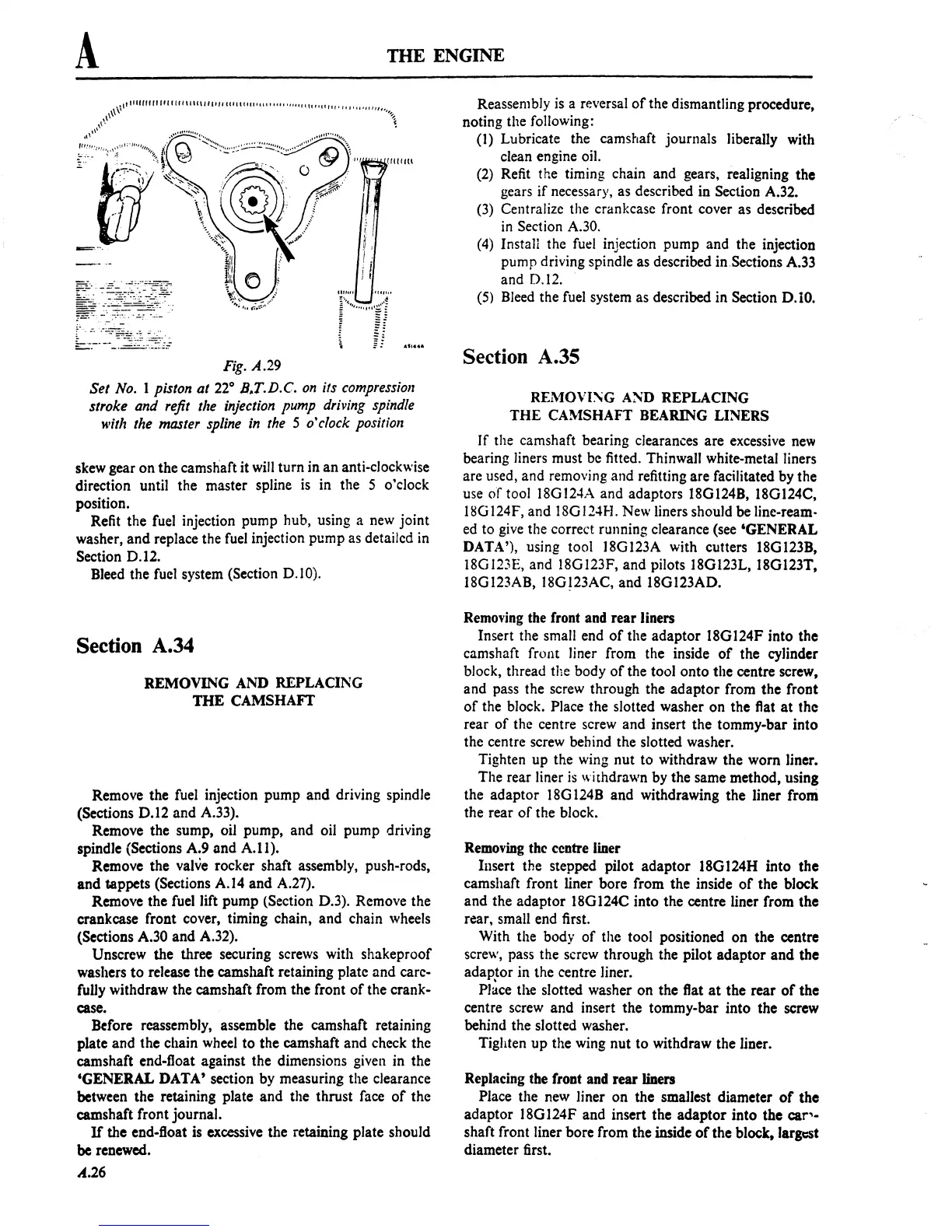
Fig.
A.29
Set No.
I piston at
22°
B.T.D.C.
on
its compression
stroke and refit
the injection pump driving spindle
with the master spline
in
the 5 o'clock position
skew gear
on
the camshaft it
will
turn in
an
anti-clockwise
direction until the master spline
is
in the 5 o'clock
position.
Refit the fuel injection pump hub, using a new joint
washer,
and
replace the
fuel
injection pump
as
detailcd in
Section D.12.
Bleed the fuel system (Section D.I 0).
Section
A.34
REMOVING AND REPLACING
THE
CAMSHAFT
Remove the fuel injection pump and driving spindle
(Sections
D.l2
and A.33).
Remove the sump, oil pump, and oil pump driving
spindle (Sections A.9
and
A.II).
Remove the valve rocker shaft assembly, push-rods,
and
tappets (Sections A.14
and
A.27).
Remove the fuel lift pump (Section D.3). Remove the
crankcase front cover, timing chain, and chain wheels
(Sections A.30 and A.32).
Unscrew the three securing screws with shakeproof
washers
to
release the camshaft retaining plate and carc-
fully withdraw the camshaft from the front
of
the crank-
case.
Before reassembly, assemble the camshaft retaining
plate and the chain wheel to the camshaft and check the
camshaft end-float against the dimensions given in the
'GENERAL DATA' section by measuring the clearance
between the retaining plate and the thrust face
of
the
camshaft front journal.
If
the end-fioat is excessive the retaining plate should
be renewed.
A.26
Reassem
bJy
is
a reversal
of
the dismantling procedure,
noting the following:
(I)
Lubricate the camshaft journals liberally with
clean engine oil.
(2)
Refit the timing chain and gears. realigning the
gears
if
necessary, as described in Section A.32.
(3) Centralize the crankcase front cover as described
in
Section A.30.
(4) Install the fuel injection pump and the injection
pump driving spindle as described
in.Sections A.33
and D.12.
(5) Bleed the fuel system as described in Section D.10.
Section
A.35
REMOVI~G
A~D
REPLACING
THE
CAMSHAFT BEARING LINERS
If
the camshaft bearing clearances are excessive
new
bearing liners must be fitted. Thinwall white-metal liners
are used, and removing and refitting are facilitated by the
use
of
tool 18GI24A and adaptors 18G124B, 18G124C,
UsG
124F, and lSG 124H. New liners should be line-ream-
ed to give the correct running clearance (see 'GENERAL
DATA'), using tool 18Gl23A with cutters 18G123B,
18G123E, and 18G123F. and pilots 18G123L, 18G123T,
I8GI23AB. 18G!23AC. and 18Gl23AD.
Removing the front and rear liners
Insert the small end
of
the adaptor 18GI24F into the
camshaft front liner from the inside
of
the cylinder
block. thread
the body
of
the tool onto the centre screw,
and pass the screw through the
adaptor
from the front
of
the block. Place the slotted washer on the flat
at
the
rear
of
the centre screw and insert the tommy-bar into
the centre screw behind the slotted washer.
Tighten up the wing nut
to
withdraw the worn liner.
The rear liner
is
withdrawn by the same method, using
the adaptor
18G
1248 and withdrawing the liner from
the rear
of
the block.
Removing the centre liner
Insert the stepped pilot
adaptor
18G 124H into the
camshaft front liner bore from the inside
of
the block
and the adaptor 18GI24C into the centre liner from the
rear. small end first.
With the body
of
the tool positioned on the centre
screw, pass the screw through the pilot adaptor
and
the
adaptor in the centre liner.
PI~ce
the slotted washer
on
the flat
at
the rear
of
the
centre screw and insert the tommy-bar into the screw
behind the slotted washer.
Tighten
up
the wing nut to withdraw the liner.
Replacing the front and rear liners
Place the new liner on the smallest diameter
of
the
adaptor ) 8G 124F and insert the
adaptor
into the
car'-
shaft front liner bore from the inside
of
the block, largest
diameter first.
 Loading...

