THE ENGINE
A
9
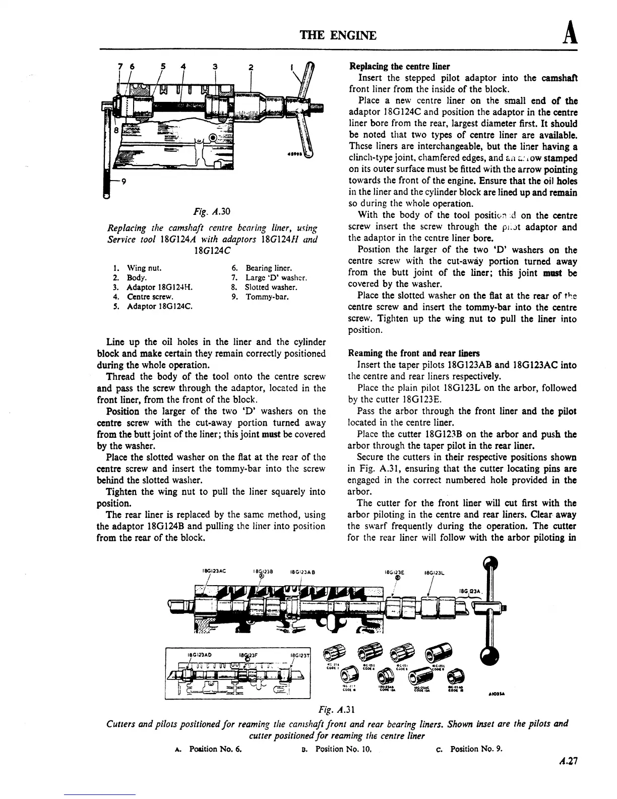
Fig.
A.30
Replacing the camshaft celllre bearing
liner,
using
Service tool
18G124A
with
adaptors 18G124Jl (md
18G124C
I.
Wing nut.
6.
Bearing liner.
2.
Body.
7.
Large
'0'
washer.
3.
Adaptor 18GI2"H.
8.
Slotted washer.
4.
Centre screw. 9. Tommy-bar.
S.
Adaptor 18G124C.
Line
up
the oil holes in the liner and the cylinder
block and make certain they remain correctly positioned
during the whole operation.
Thread the body
of
the tool onto the centre screw
and pass the screw through the adaptor, located in the
front liner, from the front
of
the block.
Position the larger
of
the two
'D'
washers on the
centre screw with the cut-away portion turned away
from the butt joint
of
the liner; this joint must
be
covered
by
the washer.
Place the slotted washer on the flat
at
the rear
of
the
centre screw and insert the tommy-bar into the screw
behind the slotted washer.
Tighten the wing nut to pull the liner squarely into
position.
The rear liner
is
replaced
by
the same method, using
the adaptor 18G124B and pulling the liner into position
from the rear
of
the block.
Replacing the
ccntre liner
Insert the stepped pilot adaptor into the camshaft
front liner from the inside
of
the block.
Place a
new
centre liner on the small end
of
the
adaptor
l8G124C and position the adaptor in the centre
liner bore from the rear, largest diameter first.
It
should
be noted that two types
of
centre liner are available.
These liners are interchangeable, but the liner having a
clinch-type
jOint. chamfered edges, and
~i'I;;':
,ow stamped
on its outer surface must be fitted with the arrow pointing
towards the front
of
the engine. Ensure that the oil holes
in
the liner and the cylinder block are lined up and remain
so during the whole operation.
With the body
of
the tool positivr1:d on the centre
screw insert the screw through the
PI;.)t adaptor and
the adaptor in the centre liner bore.
Position the larger
of
the two
'D'
washers on the
centre screw with the cut-away portion turned away
from the butt joint
of
the liner; this joint
mast
be
covered by the washer.
Place the slotted washer on the flat
at
the rear
of
t~e
centre screw and insert the tommy-bar into the centre
screw. Tighten up the wing nut
to
pull the liner into
position.
Reaming the front and rear
Iblers
Insert the taper pilots 18G123AB and 18G123AC into
the centre and rear liners respectively.
Place the plain pilot 18G123L on the arbor, followed
by
the cutter l8G123E.
Pass the arbor through the front liner and the pilot
located
in
the centre liner.
Place the cutter 18G123B on the arbor and push
the
arbor through the taper pilot in the rear liner.
Secure the cutters in their respective positions shown
in Fig. A.31, ensuring that the cutter locating pins are
engaged
in
the correct numbered hole provided in the
arbor.
The cutter for the front liner will cut first with the
arbor piloting
in
the centre and rear liners. Clear away
the swarf frequently during the operation. The cutter
for the rear liner
will
follow with the arbor piloting in
Fig.
A.Jl
Cutters and pilots positioned for reaming
the
can/shaft front and
rear
bearing
liners.
Shown
inset
are
the
pilots and
cutter positioned for reaming
the
centre liner
A. Polition
No.6.
D.
Position No.
10.
c.
Position
No.9.
A.27
 Loading...

