A
THE ENGINE
the front and centrc liners. Clear away all the swarf
before the plain pilot
is
allowed
to
enter the front liner.
When the cut in the rear liner
is
finished, free the
cutters and withdraw the arbor.
Reaming the
ceutre liner
Set
up for the second part
of
the operation by inserting
the pilots 18GI23T and 18GI23AD in the front and
rear liners. .
Pass the arbor through the pilot in the front liner and
place the cutter 18G123F on the arbor. Push the arbor
through the centre liner and the pilot located in the rear
liner.
Secure the cutter in the position shown inset in Fig.
A.31, ensuring that the locating pin
of
the cutter engages
thc correct numbered hole in the arbor.
Ream the centre liner, release the cutter, and withdraw
the arbor.
IMPORTANT.-It
is essential that the cutter
Bntes
are kept
dear
of swarf
at
aU
times during
the
cutting
operation,
preferably
witb
air-blast equipment. The
eatter sbould
be
withdrawn from
the
liner half-way
through the cut and the
&Warf
removed
from
the
cutter
and the liner.
Feed the reamer
very
slowly
and keep tbe cutters dry.
The arbor should
be
lightly lubricated before assembling
the cutters and pilots.
•
Section A.36
REMOVING
Arm
REPLACING
THE FLYWHEEL
Remove transmission (Section ).
Disconnect and label wires from starter motor and its
solenoid.
Remove starter motor with solenoid.
Remove wiring bracket from top
of
bellhousing.
Remove nuts securing the rear mounting' brackets to
flexible mount.
Take the weight
off
the rear
of
the engine preferably with a
sling attached
to
the rear lifting bracket.
Do
not jack up
under sump.
Remove capscrews and lockwashers securing bell housing to
back plate.
Remove damper plate.
Remove the 6 nuts and tab washers securing flywheel
to
the
crankshaft and remove flywheel.
When reassembling, crank the engine until the
1.4
zero
mark on the timing disc mounted on the crankshaft pulley
is
in line witb the scribed line on the pointer located on
the under side
of
the crankcase front cover. Nos. 1 and
4 pistons are now
at
T.D.C., and the
flywbeel
should
be
installed with the T.D.C.
1.4
mark
OD
its periphery
at
A.28
the top
of
the flywheel. Tighten the
flywheel
securing
nuts to the figure in the 'GENERAL DATA' section,
using torque wrench
180372.
Install the fuel injection
p~mp
as described in Section
0.12, and bleed the fuel system as described in Section
0.10.
Section A.37
REMOVING AND REPLACING
THE
ENGINE FRONT PLATE
Remove the nuts securing the engine front mounting
brackets to their flexible mounts.
Remove the crankcase front cover,
timiDg
chain, and
timing chain tensioner (Sections
A.30, A.31, and A.32).
Attach the engine by means
of
a sling
to
an overhead
lifting appliance and raise the engine
to
relieve the load
on the engine front mountings.
Unscrew the three securing screws with shakeproof
washers and remove the camshaft retaining plate. Remove
the three set screws with spring washers
and
withdraw the
front plate and joint washer
•
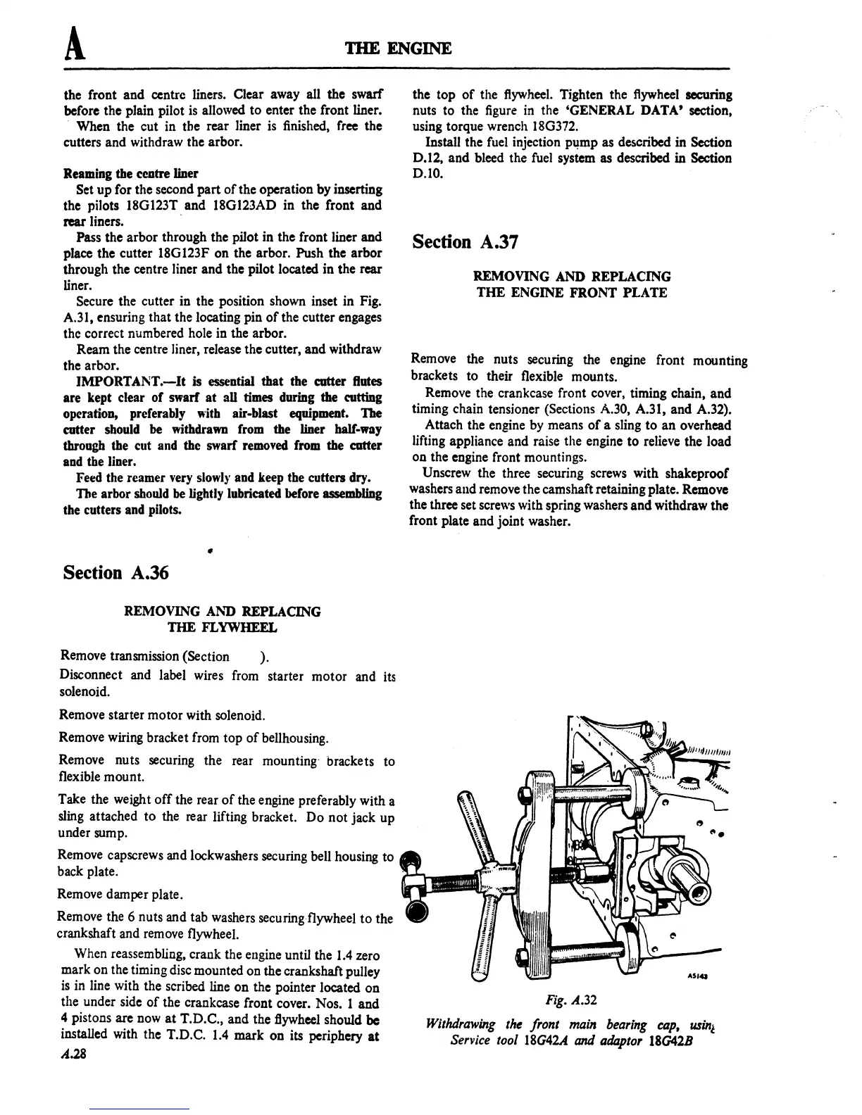
Fig.
A.32
WithdraWing
the front main bearing cap,
usin~
Service tool
18G42A
and
at/4plor 180418
 Loading...

