D
THE FUEL SYSTEM
Section
D.l
DESCRIPTION
The fuel
is
drawn from the supply tank by a mechanical
diaphragm-type lift pump,
which
is
operated by the
engine camshaft.
It
is
imperative that the
fuel
is
absolutely
free from foreign matter, and in addition to the
gauze-
type filters in the fuel lift and injection pumps a filter
of
the renewable paper element type is installed in the
feed
line from the lift pump to the inject jon pump.
The injection pump, which
is
of
the C.A.V. distributor
type, meters and forces fuel under high pressure via
Pintaux injection nozzles into the combustion chambers.
The Pintaux nozzle, which is
of
the pintle type em-
bodying an auxiliary hole to facilitate starting, has been
designed expressly for
use
with the Ricardo Comet V
type combustion chamber which
is
employed in this
engine. The
use
of
these designs ensures easy starting
under arctic conditions, especially when used in
con-
junction with the heater plugs which are fitted.
The accelerator
is
connected to the control lever on
the injection pump, which embodies a governor and
.automatic advance unit, both
of
which are hydraulically
operated.
Section D.2
DESCRIPTION
OF
THE
FUEL LIFT
PUMP
The
fuel
lift pump
is
mounted on the left-hand side
of
the crankcase and
is
operated by an eccentric on the
engine camshaft. A hand priming lever permits pumping
a supply
of
fuel
through the main
fuel
filter to the
injection pump for bleeding the system
of
air whenever
any component has been dismantled or disconnected.
As
the engine camshaft revolves, the eccentric lifts
the pump rocker arm, which moves the pull-rod together
with the diaphragm downwards against the spring'
pressure, thus creating a partial vacuum in the pumping
chamber.
Fuel drawn from the tank enters the sediment cham-
ber and then passes through
the filter gauze and the
suction
valve
into the pumping chamber. On the return
stroke the spring pressure pushes the diaphragm up-
wards, forcing the
fuel
from the pumping chamber
through the delivery valve and port to the main
fuel
filter.
When the main fuel filter
is
full a pressure
is
created
in the pump chamber. This pressure
will
hold the dia-
phragm downwards against the spring pressure, and it
will remain in this position until the main
fuel
filter
requires further
fuel.
The rocker arm operates the con-
necting link, which allows an idling movement
of
the
rocker arm when there
is
no movement
of
the
fuel
pump
diaphragm.
A spring keeps the rocker arm in constant contact
with the eccentric, thus eliminating noise.
D.4
1.
2.
3.
4.
S.
6
..
7.
8.
9.
10.
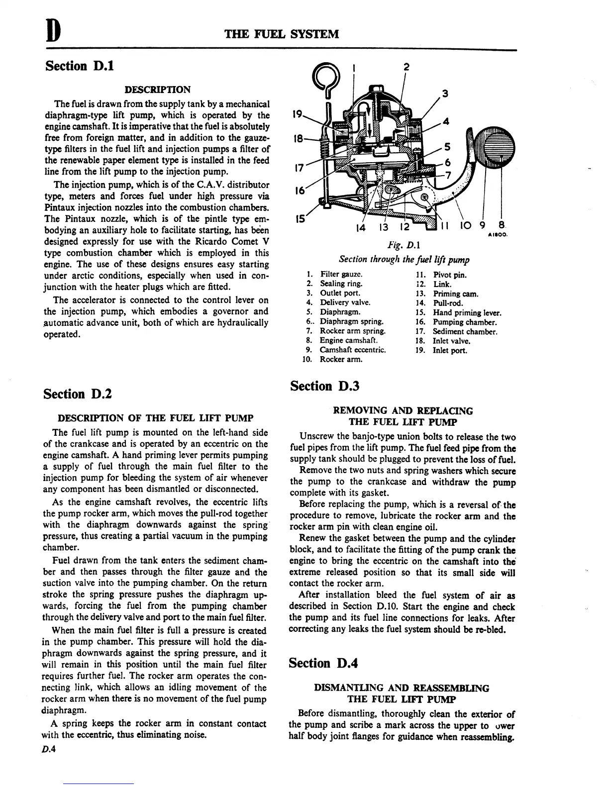
Fig.
D.l
Section
through
the
fuel lift pump
Filter gauze.
Sealing ring.
Outlet port.
Delivery valve.
Diaphragm.
Diaphragm spring.
Rocker
arm spring.
Engine
camshaft.
Camshaft eccentric.
Rocker arm.
11. Pivot pin.
12. Link.
13.
Priming cam.
14.
Pull-rod.
15.
Hand
priming lever.
16.
Pumping chamber.
17. Sediment chamber.
18. Inlet valve.
19. Inlet port.
Section D.3
REMOVING AND REPLACING
THE FUEL LIFT
PUMP
Unscrew the banjo-type union bolts to release the two
fuel pipes from the lift pump. The fuel feed pipe from the
supply tank should
be
plugged to prevent the loss
of
fuel.
Remove the two nuts and spring washers which secure
the pump to the crankcase and withdraw the pump
complete with its gasket.
Before replacing the pump, which is a reversal
of·
the
procedure to remove, lubricate the rocker arm and the
rocker arm pin with clean engine oil.
Renew the gasket between the pump and the cylinder
block, and to facilitate the fitting
of
the pump crank the
engine to bring the eccentric on the camshaft into
the
extreme released position so that its small side
will
contact the rocker arm.
After installation bleed the fuel system
of
air as
described in Section
0.10. Start the engine and check
the pump and its fuel line connections for leaks. After
correcting any leaks the fuel system should
be
re-bled.
Section D.4
DISMANTLING AND REASSEMBUNG
THE
FUEL LIFT
PUMP
Before dismantling, thoroughly clean the exterior
of
the pump and scribe a mark across the upper to
IJwer
half body joint flanges for guidance when reassembling.
 Loading...

