THE FUEL SYSTEM
D
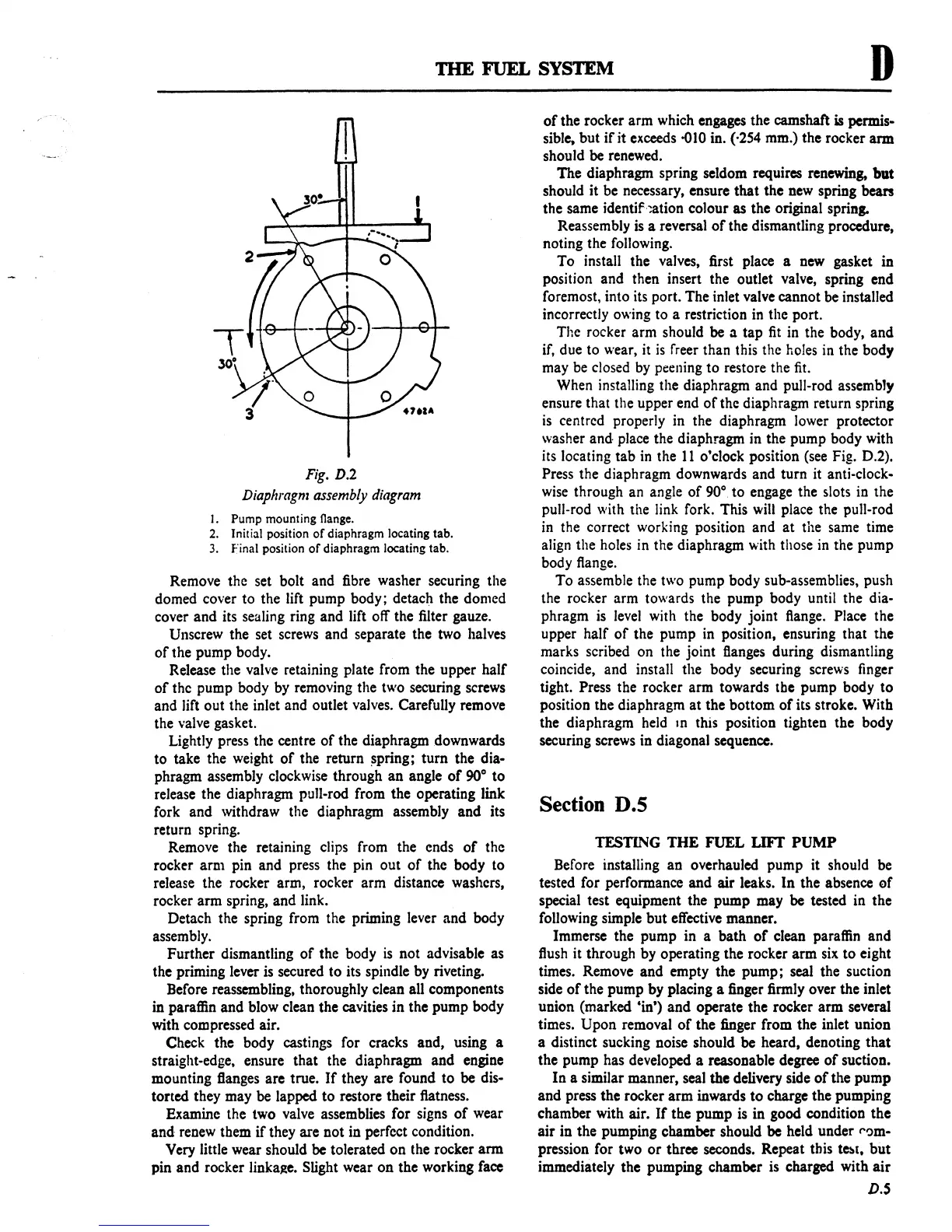
Fig.
D.2
Diaphragm
assembly
diagram
I.
Pump mounting flange.
2.
Initial position
of
diaphragm locating tab.
3.
f'inal position
of
diaphragm locating tab.
Remove the set bolt and fibre washer securing the
domed cover
to
the lift pump body; detach the domed
cover and its sealing ring and lift off the filter gauze.
Unscrew the set screws and separate the two halves
of
the pump body.
Release the valve retaining plate from the upper half
of
the pump body by removing the two securing screws
and lift out the inlet and outlet valves. Carefully remove
the valve gasket.
Lightly press the centre
of
the diaphragm downwards
to
take the weight
of
the return
~pring;
turn the dia-
phragm assembly clockwise through
an
angle
of
90°
to
release the diaphragm pull-rod from the operating link
fork and withdraw the diaphragm assembly and its
return spring.
Remove the retaining clips from the ends
of
the
rocker
arm
pin and press the pin out
of
the body to
release the rocker arm, rocker arm distance washers,
rocker arm spring, and link.
Detach the spring from the priming lever and body
assembly.
Further dismantling
of
the body
is
not advisable as
the priming lever is secured
to
its spindle by riveting.
Before reassembling, thoroughly clean all components
in paraffin and blow clean the cavities
in
the pump body
with compressed air.
Check the body castings for cracks and, using a
straight-edge. ensure that the diaphragm and engine
mounting flanges are true.
If
they are found
to
be dis-
torted they may be lapped
to
restore their flatness.
Examine the two valve assemblies for signs
of
wear
and
renew them
if
they are not in perfect condition.
Very little wear should be tolerated
on
the rocker
arm
pin and rocker linkage. Slight wear
on
the working facc
of
the rocker arm which engages the camshaft
is
permis-
sible. but
if
it exceeds
0010
in. (·254 mm.) the rocker arm
should be renewed.
The diaphragm spring seldom requires renewing, but
should it be necessary, ensure
that
the new spring bean
the same
identif.~tion
colour
as
the original spring.
Reassembly is a reversal
of
the dismantling procedure,
noting the following.
To
install the valves, first place a new gasket in
position and then insert the outlet valve, spring end
foremost, into its port. The inlet valve cannot be installed
incorrectly owing
to
a restriction in the port.
The rocker arm should be a
tap
fit
in the body, and
if, due to wear, it
is
freer than this the holes in the body
may be closed
by
peening
to
restore the
fit.
When installing the diaphragm and pull-rod assembly
ensure that the upper end
of
the diaphragm return spring
is
centred properly in the diaphragm lower protector
washer
and
place the diaphragm in the pump body with
its locating
tab
in
the
11
o'clock position (see Fig. 0.2).
Press the diaphragm downwards and turn it anti-clock-
wise through an angle
of
90°.
to
engage the slots in the
pull-rod with the link fork. This will place the pull-rod
in the correct working position and
at
the same time
align the holes in the diaphragm with those in the pump
body flange.
To
assemble the two pump body sub-assemblies. push
the rocker
arm towards the pump body until the dia-
phragm
is
level with the body joint flange. Place the
upper half
of
the pump
in
position, ensuring that the
marks scribed on the joint flanges during dismantling
coincide, and install the body securing screws finger
tight.
Press the rocker arm towards tbe pump body
to
position the diaphragm
at
the bottom
of
its stroke. With
the diaphragm held
ID
this position tighten the body
securing screws in diagonal sequence.
Section D.S
TESTING
THE
FUEL
LIFT
PUMP
Before installing an overhauled pump it should be
tested for performance and air leaks.
In
the absence
af
special test equipment the pump may be tested in the
following simple
but
effective manner.
Immerse the pump in a bath
of
clean paraffin and
flush it through by operating the rocker
arm
six
to
eight
times. Remove and empty the
pump;
seal the suction
side
of
the pump by placing a finger firmly over the inlet
union (marked 'in') and operate the rocker
arm
several
times.
Upon removal
of
the finger from the inlet union
a distinct sucking noise should be heard, denoting
that
the pump has developed a reasonable degree
of
suction.
In
a similar manner, seal the delivery side
of
the
pump
and press the rocker arm inwards
to
charge the pumping
chamber with air.
If
the pump is in good condition the
air in the pumping chamber should be held under
('~m
pression for two
or
three seconds. Repeat this
t~[,
but
immediately the pumping chamber is charged with
air
D.S
 Loading...

