D
THE FUEL SYSTEM
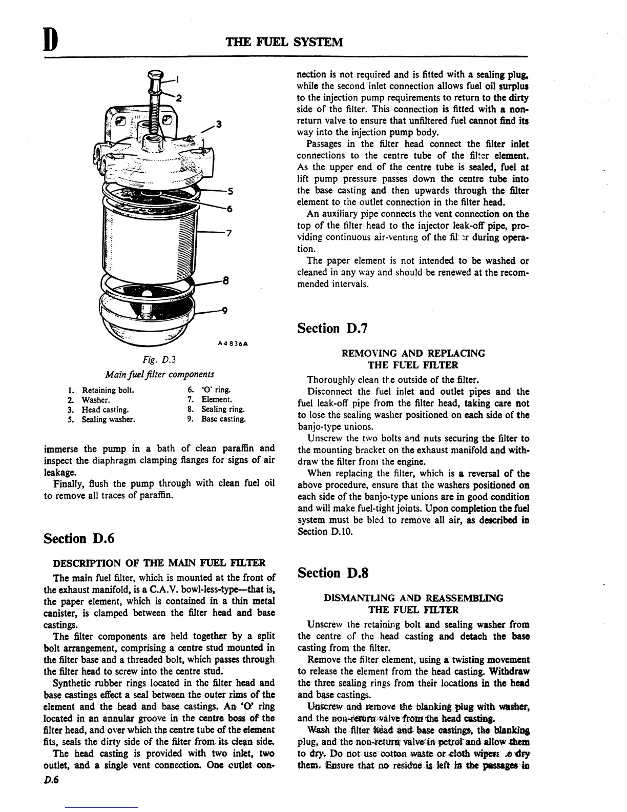
Fig. D.3
Main
fuel filter
components
1.
Retaining bolt.
6.
'0'
ring.
2.
Washer.
7.
Element.
3.
Head casting.
8.
Sealing
ring.
S.
Sealing washer.
9.
Base
caS!ing.
immerse the pump in a bath
of
clean paraffin
and
inspect the diaphragm clamping flanges for signs
of
air
leakage.
Finally, flush the
pump
through with clean fuel oil
to remove
all traces
of
paraffin.
Section D.6
DESCRIPTION
OF
TIlE
MAIN
FUEL
Fn.TER
The
main fuel filter, which
is-
mounted
at
the front
of
the exhaust manifold,
is
a C.A.V. bowl-less-type-that is,
the paper element, which
is
contained in a thin metal
canister, is clamped between the filter head
and
base
castings.
The filter components
are held together by a split
bolt arrangement, comprising a centre stud mounted in
the filter base and a threaded bolt, which passes through
the filter head
to
screw into the centre stud.
Synthetic rubber rings located in
the filter head
and
base
castings
effect
a
seal
between the outer rims
of
the
element
and
the :head
and
base castings. An'
'0'
ring
located in
an
annular groove in the
centre.
boss
of
the
filter head,
and
over which
thj::
centre tube
of
the
element
fits, seals the dirty side
of
the filter from. its
cle;\D
side.
The head
casting
is
provided with two inlet, two
outlet.
and
a single vent connection.
One
:c~et·.
con
..
D.6
nection
is
not required and
is
fitted with a sealing plug,
while the second inlet connection allows fuel oil surplus
to
the injection pump requirements
to
return
to
the dirty
side
of
the filter. This connection is fitted with a non-
return valve
to
ensure
that
unfiltered fuel cannot find its
way into the injection pump body.
Passages in the filter head connect the filter inlet
connections
to
the centre tube
of
the filter clement.
As the upper end
of
the centre tube
is
sealed, fuel
at
lift pump pressure passes down the centre tube into
the base casting and then upwards through the filter
element
to
the outlet connection in the filter head.
An auxiliary pipe connects the vent connection
on
the
top
of
the tilter head to the injector leak-off pipe, pro-
viding continuous air-venting
of
the
fiI:
_~r
during opera-
tion.
The paper element
is
not intended
to
be washed
or
cleaned in any way and should be renewed
at
the recom-
mended intervals.
Section D.7
REMOVING AND REPLACING
THE
FUEL FILTER
Thoroughly clean the outside
of
the filter.
Disconnect the fuel inlet
and
outlet pipes and the
fuel leak-off pipe from the filter head, taking care
not
to
lose the sealing washer positioned
on
each side
of
the
banjo-type unions.
Unscrew the two bolts alld nuts securing the filter
to
the mounting bracket
on
the exhaust manifold
and
with-
draw the filter from the engine.
When replacing the filter, which is
a reversal
of
the
above procedure, ensure that the washers positioned
on
each side
of
the banjo-type unions are in good condition
and will make fuel-tight joints.
Upon
completion
the
fuel
system must be bled to remove all air, as described
in
Section 0.10.
Section D.S
DISMANTLING AND REASSEMBLING
THE FUEL FILTER
Unscrew the retaining bolt
and
sealing washer from
the centre
of
the head casting
and
detach the base
casting from the filter.
Remove the filter clement, using
a twisting movement
to
release the element from the head casting. Withdraw
the three sealing rings from their locations
in the head
and
bltSe
castings.
Unscrew
and
&:tJ1l0VC!
Ute
blanking
flQg
with
_'Sher.
and the
DOn-nmtt'A,~al'\le:·fr'()IlfJftll
bead
castiD."
W.ash
Cbe.:1Ut~
~4
~d:.tN.se
castings;,
the-
blankias
plug,
andthenon..r~lIrl\!
ftlvefiR IlCtrot
and
:allow .cbm
to
dty.
Do
not'
user
oottoowa&k
-
or
.etotb wiperi'
;;e
'Cby
them. :Easure
that.llD
residuens· left
ia
the
passaPS'ia
 Loading...

