THE FUEL SYSTEM
D
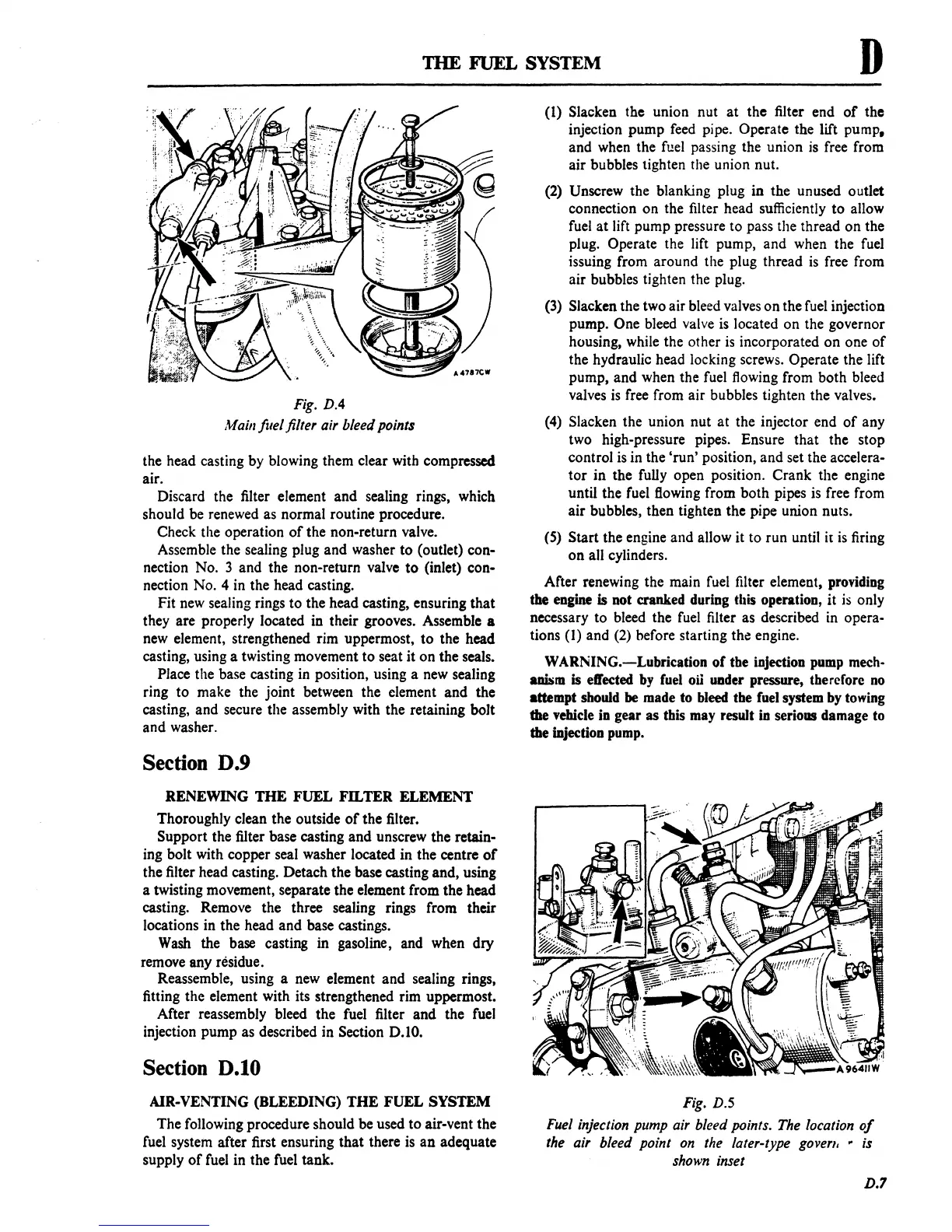
Fig. D.4
Main ftlel filter air bleed points
the head casting by blowing them clear with compressed
air.
Discard the filter element and sealing rings, which
should be renewed as normal routine procedure.
Check the operation
of
the non-return valve.
Assemble the sealing plug
and
washer
to
(outlet) con-
nection No. 3 and the non-return valve
to
(inlet) con-
nection No.
4 in the head casting.
Fit new sealing rings
to
the head casting, ensuring
that
they are properly located in their grooves. Assemble a
new element, strengthened rim uppermost,
to
the head
casting, using a twisting movement
to
seat it
on
the seals.
Place the base casting in position, using a new sealing
ring
to
make the joint between the element
and
the
casting, and secure the assembly with the retaining bolt
and
washer.
Section D.9
RENEWING
THE
FUEL
FaTER
ELEMENT
Thoroughly clean the outside
of
the filter.
Support the filter base casting
and
unscrew the retain-
ing bolt with copper seal washer located in the centre
of
the filter head casting. Detach the base casting and, using
a twisting movement, separate the element from the head
casting. Remove the three sealing rings from their
locations in the head
and
base castings.
Wash the base casting in gasoline, and when dry
remove any residue.
Reassemble, using a new element and sealing rings,
fitting the element with its strengthened rim uppermost.
After reassembly bleed the fuel filter
and
the fuel
injection pump as described in
Section
0.10.
Section 0.10
AIR-VENTING (BLEEDING)
THE
FUEL SYSTEM
The
following procedure should be used
to
air-vent the
fuel system after first ensuring that there is
an
adequate
supply
of
fuel in the fuel tank.
(1) Slacken the union nut
at
the filter end
of
the
injection pump feed pipe.
Operate the lift pump.
and when the fuel passing the union is free from
air bubbles tighten the union nut.
(2)
Unscrew the blanking plug in the unused outlet
connection
on
the filter head sufficiently
to
allow
fuel
at
lift pump pressure
to
pass the thread
on
the
plug.
Operate the lift pump, and when the fuel
issuing from around the plug thread
is
free from
air bubbles tighten the plug.
(3) Slacken the two air bleed valves
on
the fuel injection
pump.
One bleed valve is located
on
the governor
housing, while the other
is
incorporated
on
one
of
the hydraulic head locking screws. Operate the lift
pump,
and
when the fuel flowing from both bleed
valves
is
free from air bubbles tighten the valves.
(4) Slacken the union nut at the injector end
of
any
two high-pressure pipes. Ensure that the stop
control is in the
'run'
position, and set the accelera-
tor
in the fully open position. Crank the engine
until the fuel flowing from
both
pipes is free from
air
bubbles, then tighten the pipe union nuts.
(S) Start the engine and allow it to run until it
is
firing
on
all cylinders.
After renewing the main fuel filter element, providing
the
engine is not cranked during this operation,
it
is
only
necessary
to
bleed the fuel filter as described in opera-
tions
(1) and (2) before starting the engine.
WARNING.-Lubrication
of
tbe injection pump mech-
aDbim
is effected
by
fuel oil
UDder
pressure, tberefore
no
attempt should be made
to
bleed tbe fuel system by towing
the vehicle in gear as tbis may result in serious damage to
tbe iDjection pump.
Fig.
D.S
Fuel injection pump air bleed points. The location
of
the air bleed point
on
the later-type goven. p is
shown inset
D.?
 Loading...

