D
THE FUEL SYSTEM
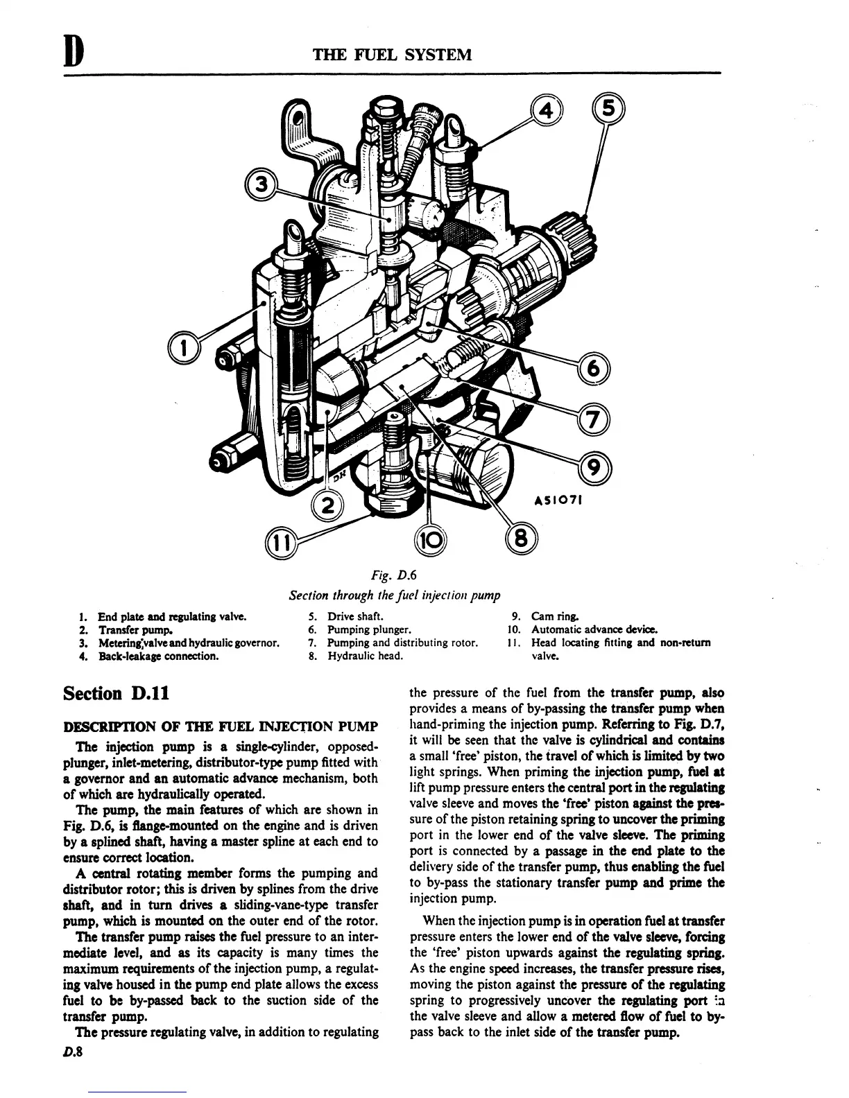
Fig. D.6
I. End plate
aDd
regulating valve.
Section through the juel injection pump
S.
Drive shaft.
9.
Cam ring.
2. Transfer pump.
6.
Pumping plunger.
10.
Automatic advance device.
3. Metcring;valve and hydraulic governor.
4. Back-leakage
connection.
7.
Pumping and distributing rotor.
S.
Hydraulic head.
I
I . Head locating fitting and non-return
valve.
Section
D.II
DFSCRIPrION OF THE FUEL INJECl10N PUMP
The
jnjection
pump
js
a single-cylinder, opposed-
plunger, inlet-metering, distributor-type pump fitted with
a governor and
an
automatic advance mechanism, both
of
which are hydraulically operated.
The pump, the main features
of
which are shown in
Fig. D.6,
is
ftange-mounted
on
the engihe and is driven
by a splined shaft, having a master spline
at
each end
to
ensure correct location.
A central rotating member forms the pumping and
distributor
rotor;
this is driven by splines from the drive
shaft,
and
in
turn
drives a sliding-vane-type transfer
pump, which is mounted
on
the outer end
of
the rotor.
The transfer pump raises the fuel pressure
to
an
inter-
mediate level, and as its capacity is many times the
maximum requirements
of
the injection pump, a regulat-
ing
valve housed
in
the pump end plate allows the excess
fuel
to
be by-passed back
to
the suction side
of
the
transfer pump.
The
pressure regulating valve, in addition
to
regulating
D.S
the pressure
of
the fuel from the transfer pump, also
provides a means
of
by-passing the transfer
pump
when
hand-priming the injection pump.
Referring
to
Fig. D.7,
it will
be
seen that the valve is cylindrical
and
contains
a small 'free' piston, the travel
of
which is limited
by
two
light springs. When priming the injection pump, fuel
at
lift pump pressure enters the central
port
in the regulating
valve sleeve and moves the 'free' piston against the pres-
sure
of
the piston retaining spring
to
uncover the priming
port
in
the lower end
of
the valve sleeve. The priming
port
is
connected by a passage in the end plate
to
the
delivery side
of
the transfer pump, thus enabling
the
fuel
to by-pass the stationary transfer pump
and
prime the
injection pump.
When the injection pump
is
in operation fuel
at
transfer
pressure enters the lower end
of
the valve sleeve, forcing
the 'free' piston upwards against the regulating spring.
As the engine speed increases, the transfer pressure rises,
moving the piston against the pressure
of
the regulating
spring
to
progressively uncover the regulating
port
::1
the valve sleeve and allow a metered flow
of
fuel
to
by-
pass back to the inlet side
of
the transfer pump.