THE FUEL SYSTEM
D
B
Fig.
D.7
Sectioll
throllg17
tfle
end-plate alld reguhllillg \'ah'e
A. Priming.
7.
Regulating riSk,n.
n.
Regulating.
8.
Piston retaining spring.
I.
J nlet
conned
inn. 9.
Fud
passage
hl
transfer
2.
Sleeve retaining spring.
pump
inlet.
3.
Nylon filter.
10.
Regulating port.
4. Sleeve guide
plug.
11.
Fuel passag\: to transfer
5.
Regulating spring.
pump
nutlet.
6. Regulating slee\'e.
The transfer pressure, therefore,
is
controlled by a
balance between the regulating spring pressure and the
requirements
of
the injection pump
at
any moment.
The pumping and distributing rotor revolves, and
is
a
close fit, in the stationary
hydraulic head. Thc pumping
section
of
the
rotor
has a transverse bore containing
twin opposed pumping plungers. These plungers are
operated by means
of
a cam ring, carried in the pump
housing, through rollers and shoes which slide
in
the
rotor. The cam ring has four internal lobes operating
in diagonally opposite pairs. The opposed plungers have
no
return springs but are moved outwards
by
fuel under
pressure from the transfer pump, the
flow
of
fuel and
outward displacement
of
the plungers being determined
by the setting
of
the metering valve and the speed
at
which the pump
is
rotating. As a result the rollers, which
operate the plungers, do not follow the contour
of
the
internal cam ring entirely,
but
will
contact the cam lobes
at
points which
will
vary according to the amount
of
plunger displacement.
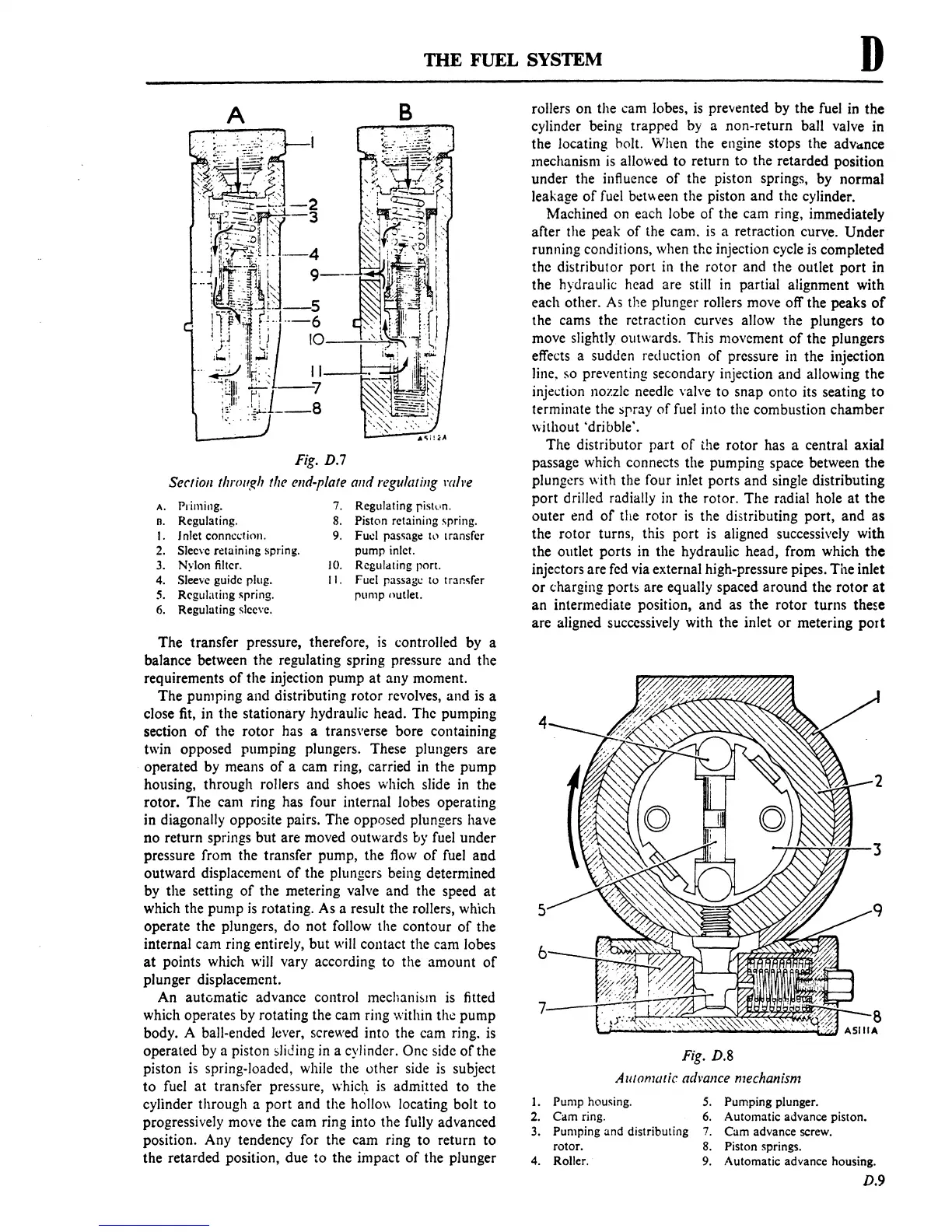
An
automatic advance control
mechani5lTI
is
fitted
which operates by rotating the cam ring within the pump
body. A ball-ended lever, screwed into the cam ring.
is
operated by a piston sliding in a cylinder. One side
of
the
piston
is
spring-loaded, while the other side
is
subject
to
fuel
at
transfer pressure, which
is
admitted to the
cylinder through a
port
and the hollo\\ locating bolt to
progressively move the cam ring into the fully advanced
position. Any tendency for the cam ring to return to
the retarded position, due to the impact
of
the plunger
rollers
on
the cam lobes,
is
prevented by the fuel in the
cylinder being trapped by a non-return ball valve in
the locating holt. When the engine stops the
adv"nce
mechanism
is
allowed to return to the retarded position
under the influence
of
the piston springs, by normal
leakage
of
fuel bct\l,een the piston and the cylinder.
Machined on each lobe
of
the cam ring, immediately
after the peak
of
the cam.
is
a retraction curve.
Under
running conditions, when thc injection cycle
is
completed
the distributor
port
in
the rotor and the outlet
port
in
the hydraulic head are still in partial alignment with
each other. As the plunger rollers move off the peaks
of
the cams the retraction curves allow the plungers
to
move slightly outwards. This movement
of
the plungers
effects a sudden reduction
of
pressure in the injection
line,
so preventing secondary injection and allowing the
injedion nozzle needle valve to snap onto its seating
to
terminate the spray
of
fuel into the combustion chamber
without 'dribble'.
The distributor part
of
the rotor has a central axial
passage which connects the pumping space between
the
plungers with the four inlet ports and single distributing
port drilled radially in the rotor. The radial hole at the
outer end
of
the rotor
is
the distributing port,
and
as
the rotor turns, this port
is
aligned successively with
the outlet ports in the hydraulic head, from which
the
injectors are fed via external high-pressure pipes. The inlet
or
charging ports are equally spaced around the
rotor
at
an intermediate position, and as the rotor turns these
are aligned successively with the inlet
or
metering
port
4
5
6
Fig.
D.8
Alllomaric
Q(h'ance
mechanism
1. Pump housing.
2.
Cam
ring.
3.
Pumping
and
distributing
rotor.
4. Roller.
5.
Pumping plunger.
6.
Automatic advance piston.
7.
Cam
advance screw.
8.
Piston springs.
9.
Automatic advance housing.
D.9
 Loading...

