D
THE FUEL SYSTEM
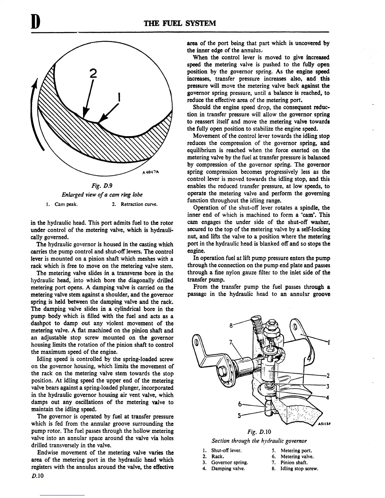
Fig.
D.9
Enlarged
'View
of
a cam
ring
lobe
I.
Cam
peak.
2.
Retraction curve.
in the hydraulic head. This
port
admits fuel
to
the
rotor
under control
of
the metering valve, which is hydrauli-
cally governed.
The
hydraulic governor
is
housed in the casting which
carries the pump control
and
shut-off levers.
The
control
lever is mounted
on
a pinion shaft which meshes with a
rack which is free
to
move
on
the metering valve stem.
The metering valve slides in a transverse bore in the
hydraulic head, into which bore the diagonally driUed
metering
port
opens. A damping valve is carried
on
the
metering valve stem against a shoulder, and the governor
spring
is
held between the damping valve
and
the rack.
The damping valve slides
in
a cylindrical
bore
in the
pump body which is filled with the fuel
and
acts as a
dashpot
to
damp
out
any violent movement
of
the
metering valve. A flat machined
on
the pinion shaft
and
an
adjustable stop screw mounted
on
the governor
housing limits the rotation
of
the pinion shaft
to
control
the maximum speed
of
the engine.
Idling speed
is
controlled by the spring-loaded screw
on
the governor housing, which limits the movement
of
the rack
on
the metering valve stem towards the stop
position.
At
idling speed the upper end
of
the metering
valve bears against a spring-loaded plunger, incorporated
in the hydraulic governor housing
air
vent valve, which
damps
out
any oscillations
of
the metering valve
to
maintain the idling speed.
The governor is operated by fuel
at
transfer pressure
which
is
fed from the annular groove surrounding the
pump rotor. The fuel passes through the hollow metering
valve into an annular space around the valve via holes
drilled transversely in the valve.
Endwise movement
of
the metering valve varies the
area
of
the metering
port
in the hydraulic head which
registers with the annulus around the valve, the effective
D.IO
area
of
the
port
being that
part
which is uncovered
by
the inner edge
of
the annulus.·
When the control lever is moved
to
give increased
speed the metering valve is pushed
to
the fully open
position by the governor spring. As the engine speed
increases, transfer pressure increases also,
and
this
pressure will move the metering valve back against
the
governor spring pressure, until a balance is reached,
to
reduce the effective area
of
the metering port.
Should the engine speed drop, the consequent reduc-
tion in transfer pressure will allow the governor spring
to
reassert itself and move the metering valve towards
the fully open position
to
stabilize the engine speed.
Movement
of
the control lever towards the idling stop
reduces the compression
of
the governor spring,
and
equilibrium is reached when the force exerted
on
the
metering valve by the fuel
at
transfer pressure is balanced
by compression
of
the governor spring.
The
governor
spring compression becomes progressively less as the
control lever
is
moved towards
tht
idling stop,
and
this
enables the reduced transfer"pressure,
at
low speeds,
to
operate the metering valve and perform the governing
function throughout the idling range.
Operation
of
the shut-off lever rotates a spindle, the
inner end
of
which is machined
to
form a 'cam'. This
cam engages the under side
of
the shut-off washer,
secured to the
top
of
the metering valve by a self-locking
nut,
and
lifts the valve
to
a position where the metering
port
in the hydraulic head is blanked off
and
so stops the
engine.
In
operation fuel
at
lift pump pressure enters the
pump
through the connection
on
the pump end plate
and
passes
through a fine nylon gauze filter
to
the inlet side
of
the
transfer pump.
From
the transfer pump the fuel passes through a
passage in the hydraulic head
to
an
annular groove
Fig.
D.1O
Section
through
the
hydraulic
go
'Vernor
1. Shut-off
lever.
S.
Metering port.
2.
Rack.
6.
Metering
valve.
3.
Governor spring.
7.
Pinion shaft.
4. Damping
valve.
8.
Idling stop
screw.
 Loading...

