TIlE FUEL SYSTEM
D
A
B
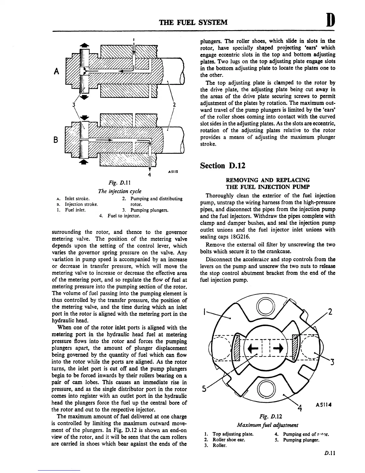
A.
Inlet stroke.
B. Injection stroke.
1.
Fuel inlet.
Fig.
D.ll
The
injection
cycle
2.
Pumping and distributing
rotor.
3.
Pumping plungers.
4.
Fuel to injector.
surrounding the rotor, and thence to the governor
metering valve. The position
of
the metering valve
depends upon the setting
of
the control lever, which
varies the governor spring pressure on the valve. Any
variation in pump speed
is
accompanied
by
an increase
or decrease
in
transfer pressure, which
will
move the
metering valve to increase or decrease the
effective
area
of
the metering port, and
so
regulate the
flow
of
fuel
at
metering pressure into the pumping section
of
the rotor.
The volume
of
fuel
passing into the pumping element
is
thus controlled by the transfer pressure, the position
of
the metering valve, and the time during which an inlet
port
in
the rotor
is
aligned with the metering port in the
hydraulic head.
When one
of
the rotor inlet ports
is
aligned with the
metering port in the hydraulic head fuel
at
metering
pressure
flows
into the rotor and forces the pumping
plungers apart, the amount
of
plunger displacement
being governed by the quantity
of
fuel
which can
flow
into the rotor while the ports are aligned.
As
the rotor
turns, the inlet port
is
cut off and the pump plungers
begin to be forced inwards by their rollers bearing
on
a
pair
of
cam lobes. This causes an immediate rise in
pressure, and as the single distributor port in the rotor
comes into register with an outlet port in the hydraulic
head the plungers force the
fuel
up the central bore
of
the .rotor and out to the respective injector.
The maximum amount
of
fuel
delivered
at
one charge
is
controlled by limiting the maximum outward move-
ment
of
the plungers. In Fig. D.12
is
shown an end-on
view
of
the rotor, and it
will
be seen that the cam rollers
are carried in shoes which bear against the ends
of
the
plungers. The roller shoes, which slide in slots in the
rotor, have specially shaped projecting 'ears' which
engage eccentric slots in the top and bottom adjusting
plates. Two lugs on the top adjusting plate engage slots
in the bottom adjusting plate to locate the plates one to
the other.
The top adjusting plate
is
clamped to the rotor by
the drive plate, the adjusting plate being cut away in
the areas
of
the drive plate securing screws to permit
adjustment
of
the plates by rotation. The maximum out-
ward travel
of
the pump plungers
is
limited by the 'ears'
of
the roller shoes coming into contact with the curved
slot sides
in
the adjusting plates.
As
the slots are eccentric,
rotation
of
the adjusting plates relative to the rotor
provides a means
of
adjusting the maximum plunger
stroke.
Section D.12
REMOVING
AND
REPLACING
THE FUEL
INJECDON
PUMP
Thoroughly clean the exterior
of
the
fuel
injection
pump, unstrap the wiring harness from the high-pressure
pipes, and disconnect the pipes from the injection pump
and the
fuel
injectors. Withdraw the pipes complete with
clamp and damper bushes, and seal the injection pump
outlet unions and the
fuel
injector inlet unions with
sealing caps
18G216.
Remove the external oil filter by unscrewing the two
bolts which secure it to the crankcase.
Disconnect the accelerai.or and stop controls from the
levers
on the pump and unscrew the two nuts to release
the stop control abutment bracket from the end
of
the
fuel
injection pump.
5
Fig.
D.l2
Maximum fuel adjustment
1. Top adjusting plate.
4.
Pumping end
of
r·,t')r.
2.
RoUer
shoe ear.
S.
Pumping plunger.
3.
Roller;
D.ll
 Loading...

