D
THE FUEL SYSTEM
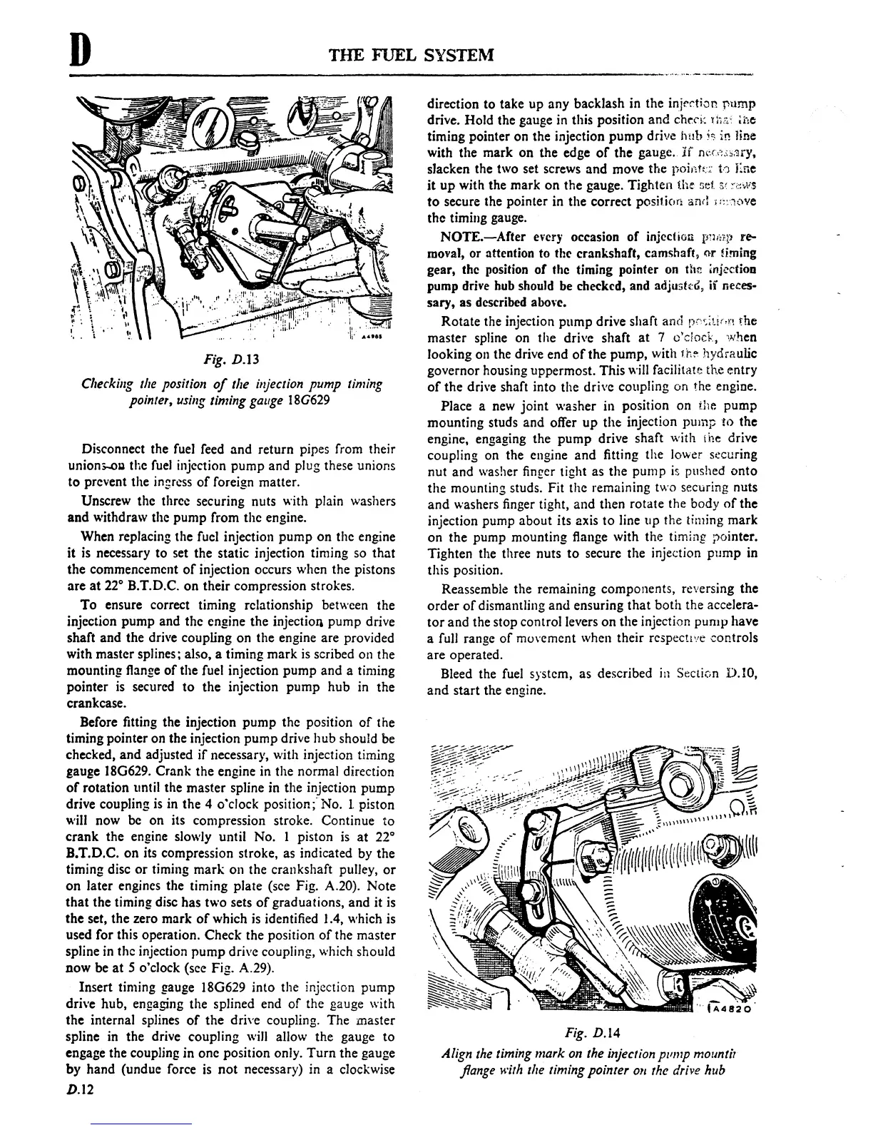
Fig. D.13
Checkillg the position
of
the injection pump timing
pointer,
usillg timing gauge
18G629
Disconnect
the
fuel feed
and
return
pipes from their
union:;..og the fuel injection
pump
and
plug these unions
to
prevent
the
ingress
of
foreign matter.
Unscrew
the
three securing nuts with plain washers
and
withdraw
the
pump
from
the
engine.
When
replacing
the
fuel injection
pump
on
the
engine
it
is necessary
to
set
the
static
injection timing so
that
the
commencement
of
injection occurs when
the
pistons
are
at
22° B.T.D.C.
on
their
compression strokes.
To
ensure correct timing relationship between
the
injection
pump
and
the
engine
the
injection
pump
drive
shaft
and
the
drive coupling
on
the
engine
are
provided
with
master splines; also, a timing
mark
is scribed on
the
mounting
flange
of
the
fuel injection
pump
and
a timing
pointer
is secured
to
the
injection
pump
hub
in
the
crankcase.
Before fitting
the
injection
pump
the
position
of
the
timing
pointer
on
the
injection
pump
drive
hub
should be
checked,
and
adjusted
if
necessary, with injection timing
gauge 18G629.
Crank
the
engine in
the
normal
direction
of
rotation
until
the
master
spline in
the
injection
pump
drive coupling is in
the
4
o'clock
position;-
No.
1.
piston
will
now
be
on
its compression stroke.
Continue
to
crank
the
engine slowly
until
No.
1
piston
is
at
2r
B.T.D.C.
on
its compression stroke, as indicated
by
the
timing disc
or
timing
mark
on
the
crankshaft
pulley,
or
on
later
engines
the
timing
plate
(see Fig. A.20).
Note
that
the
timing disc
has
two
sets
of
graduations,
and
it
is
the
set,
the
zero
mark
of
which is identified 1.4, which is
used
for
this operation.
Check
the position
of
the
master
spline in
the
injection
pump
drive coupling, which
should
DOW
be
at
5 o'clock (see Fig. A.29).
Insert
timing gauge 18G629
into
the injection
pump
drive
hub,
engaging
the
splined
end
of
the
gauge with
the
internal splines
of
the
drive coupling.
The
master
spline in
the
drive
coupling
will allow
the
gauge
to
engage the coupling
in
one
position
only.
Turn
the
gauge
by
hand
(undue force is
not
necessary) in a clockwise
D.l2
direction
to
take
up
any
backlash
in
the
injection
pump
drive.
Hold
the
gauge in this position
and
chrn:
n,';: ti,e
timing
pointer
on
the
injection
pump
drive
h!lb
is
in
line
with
the
mark
on
the
edge
of
the
gauge.
if
n\:U;,i,;~ry.
slacken the two set screws
and
move
the
poiM:::'
t')
Ene
it
up
with
the
mark
on
the
gauge.
Tighten
I.he
:;eI
SI
~',~W,S
to
secure the
pointer
in
the
correct
position and i
,,:,~(we
the
timing gauge.
NOTE.-After
every occasion
of
injcclioll
l"M,P
re-
moval, or attention to the crankshaft, camshaft,
or
liming
gear, the position
of
the timing pointer on
th(;
injection
pump drive bub should be checked, and adjusttG, if nel:es-
sary,
as described abol·e.
Rotate
the injection
pump
drive shaft
and
pr'<;;t!(,n
the
master
spline on
the
drive
shaft
at
7 o'clock, 'when
looking
on
the
drive
end
of
the
pump,
with
jh~
hydraulic
governor
housing
uppermost.
This
will facilitau: the
entry
of
the
drive shaft
into
the
drive
coupling
on
the engine.
Place
a new
joint
washer
in
position
on
the
pump
mounting
studs
and
offer
up
the
injection
pump
to
the
engine, engaging
the
pump
drive
shaft
with the drive
coupling on
the
engine
and
fitting
the
lower securing
nut
and
washer finger tight as
the
pump
i$
pushed
onto
the
mounting
studs. Fit
the
remaining two securing nuts
and
washers finger tight,
and
then
rotate
the
body
of
the
injection
pump
about
its
axis
to
line tip
the
timing
mark
on
the
pump
mounting
flange with
the
timing
}">ointer.
Tighten
the three
nuts
to
secure
the
injection
pump
in
this position.
Reassemble
the
remaining
components,
reversing
the
order
of
dismantling
and
ensuring
that
both
the
accelera-
tor
and
the
stop
control
levers
on
the
injection
pump
have
a full range
of
muvement when
their
rcspectt'!c
controls
are
operated.
Bleed the fuel system, as described
ill
SecLiGn
D.
IO,
and
start
the engine.
Fig. D.14
Align the timing mark on the injection pllmp
mOllntil
flange with the timing pointer
011
the drive hllb
 Loading...

