The magneto is a typical flywheel magneto which generates electricity for ignition and lighting.
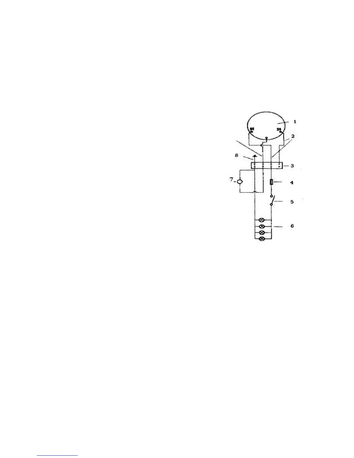
Figure 7 explains the lighting fixture as well as ignition switch diagram. In order to prevent lamp
burn-outs. the total effect of lamps should be exactly 16W (6v). when alternating current is used
for lighting purposes. switching should be made to one yellow wire only (see Fig. 7).
(The following Is furnished for those interested in more magneto information. The Westerbeke
Recommended Wiring Diagram #1523? is shown on Page 12.)
1. Magneto
2. 6 to 8 volt output (AC)
3. Connecting Block
4. Fuse*
5. Load Switch*
6. Lamp/resistance Load (to prevent burn-
out of lamps, the total load must be 16 watts)
7. Magneto grounding switch
8. Engine Ground
* not furnished
Figure 7 - Magneto
Starter Generator
A belt connects the engine crank shaft and the motor generator. When starting the motor
generator acts as a starting engine taking the required power from a 12V battery. which is part of
the electric system. When running the motor generator acts as a generator. generating electricity
for the battery and other consumption points. Refer to Figure 5. Wiring diagram.
Reverse/Reduction Gear
The reverse/reduction gear is located directly behind The engine. The PTO shaft, which is at a
level below the crank shaft. has bearings absorbing shaft loads created by the thrust of the
propeller. Forward and reverse gear are engaged by means of a taper drive cone type clutch.
There are no transfer gears in the construction. The gear wheel type water pump has been placed
with the gear box.