3.4. Connector Information
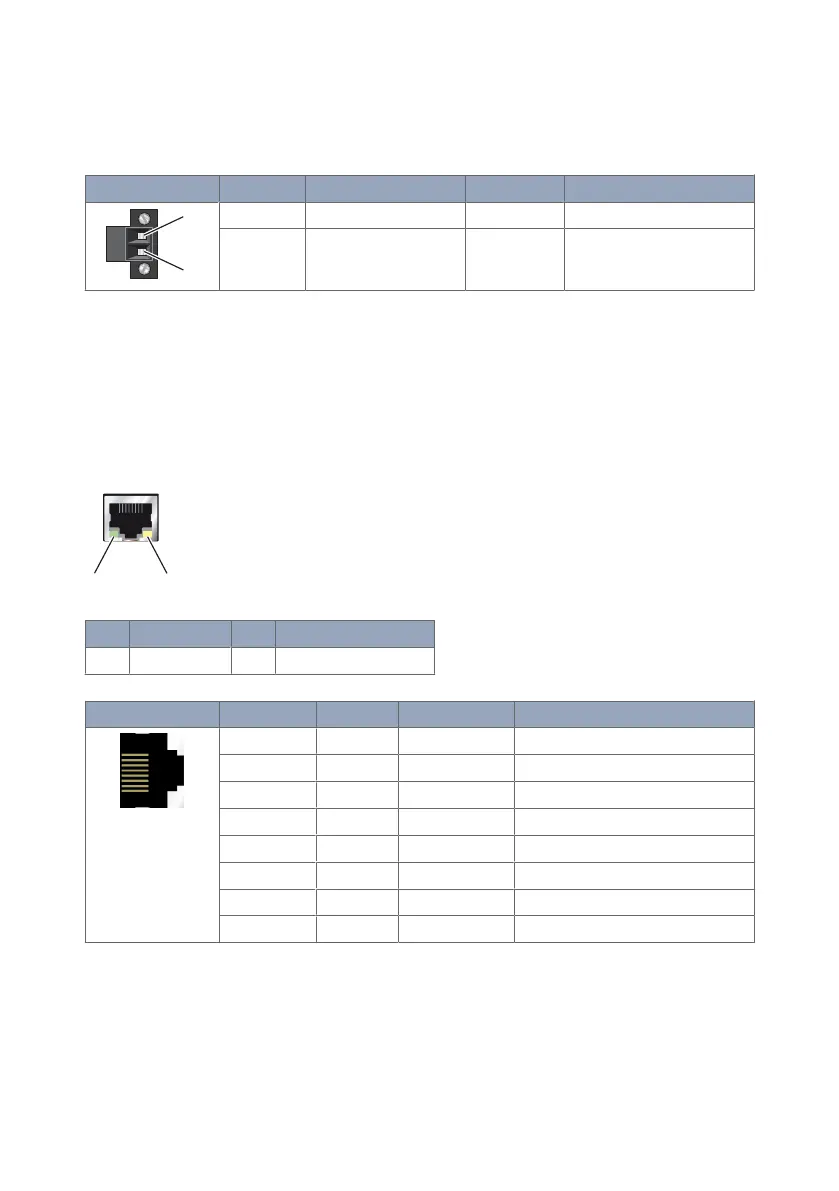
3.4.1. DC Power Connection
Illustration
Position Product marking Direction Description
1 - Input Common
2 + Input Supply voltage input DC
Table 4. Power input
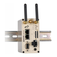
3.4.2. Ethernet
The Ethernet ports are on the front of the unit and are marked LAN 1 and LAN 2. Each
port has a LED indicating the connection speed and a LED indicating activity. Both ports
are capable of auto-negotiation, meaning cross-over cables are not required. The Ethernet
ports are switched, allowing more than one Ethernet device to be connected to the unit at
one time.
No.
Description No. Description
1 Activity LED 2 Connection speed LED
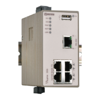
Illustration Pin no. Signal Direction Description
1 TD+ In/Out Transmitted/Received data
2 TD- In/Out Transmitted/Received data
3 RD+ In/Out Transmitted/Received data
4 - - Not connected
5 - - Not connected
6 RD- In/Out Transmitted/Received data
7 - - Not connected
8 - - Not connected
Table 5. Ethernet TX connections (RJ-45 connector), LAN 1-2
10 MRD-415 and MRD-455