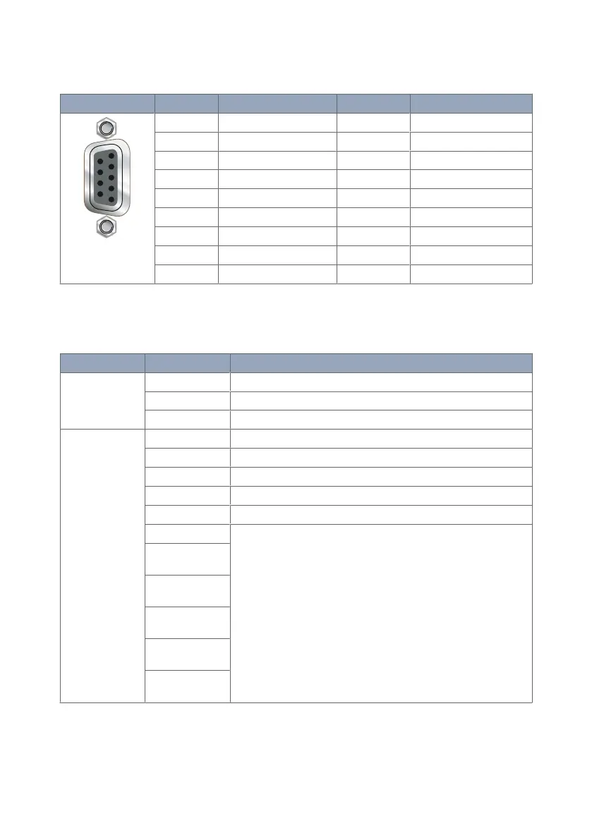
3.4.3. Serial Port (DCE Female)
Illustration Position Product marking Direction Description
1 DCD Out Data Carrier Detect
2 RxD Out Recieve Data
3 TxD In Transmit Data
4 DTR In Data Terminal Ready
5 SG - Signal Ground
6 DSR Out Data Set Ready
7 RTS In Request to Send
8 CTS Out Clear to Send
9 RJ Out Ring Indicator
Table 6. Serial Port
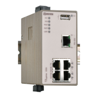
3.5. LED Indicators
LED
Status Description
STS
Status
RED No wireless network has been detected
RED FLASH A wireless network has been detected
GREEN Power up self test OK/no issues
NET
NET 1
NET 2
Network
indicator
OFF Not ready
RED RF circuitry initialising or network registration fault
GREEN/RED Network connection fault
GREEN FLASH Searching for network
GREEN Locked to network
GREEN 1 BLINK Signal strength indication:
1 - Very poor
2 - Normal
3 - Very good
GREEN 2
BLINKS
GREEN 3
BLINKS
GREEN 4
BLINKS
GREEN 5
BLINKS
GREEN 6
BLINKS
Table 7. LED indicators
MRD-415 and MRD-455 11