18
6618-2202
* Direction relative to this unit.
Leased Line
Position
D-sub
Screw
terminal
Direction* Description
D-sub
description
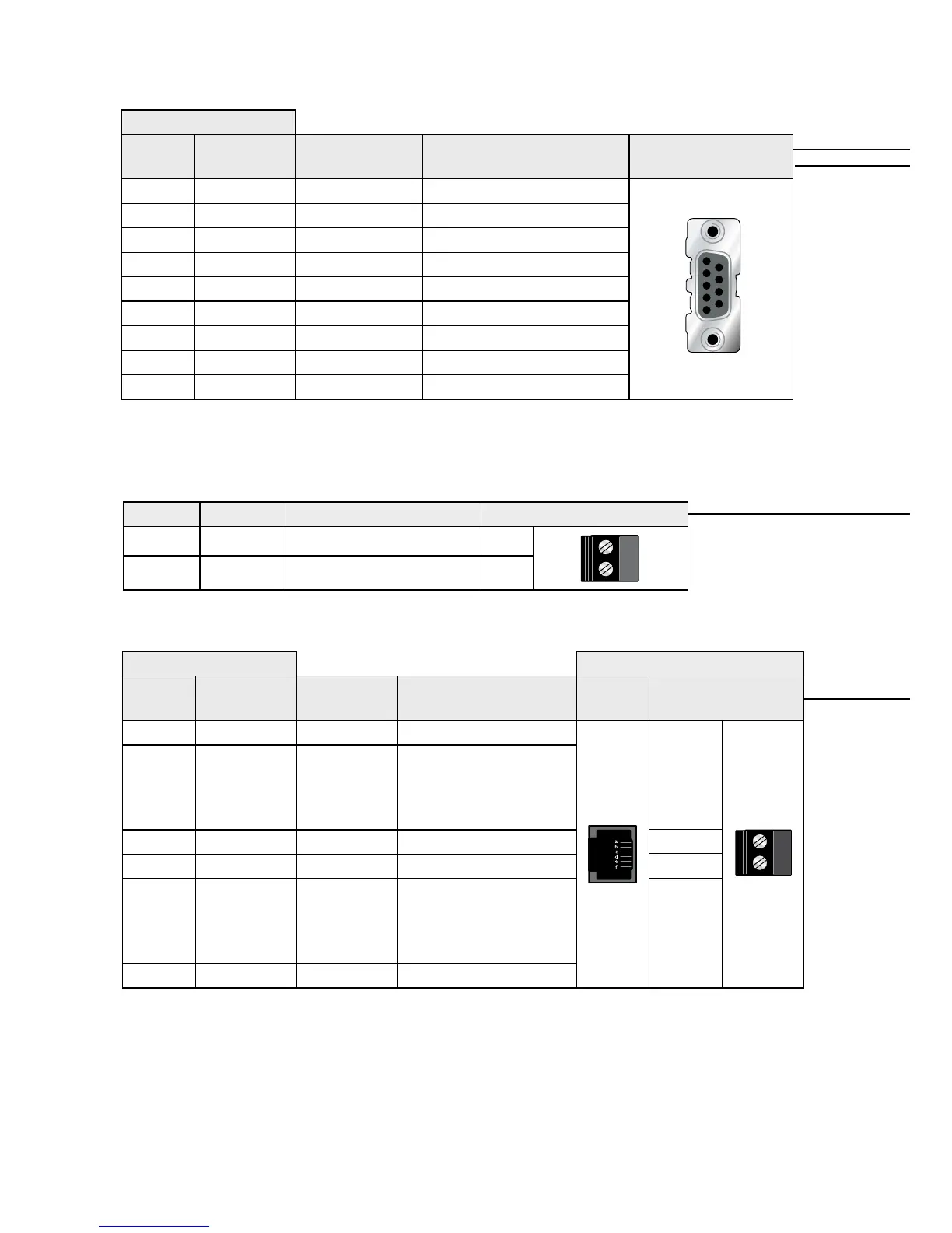
No. 1 No. 4 Outd Data Carrier Direct (DCD)
No. 2 No. 7 Out Received Data (RD)
No. 3 No. 8 In Transmitted Data (TD)
No. 4 No. 3 In Data Terminal Ready (DTR)
No. 5 No. 1 Not Connected Signal Ground (SG)
No. 6 No. 2 Out Data Set Ready (DSR)
No. 7 No. 6 In Request To Send (RTS)
No. 8 No. 5 Out Clear To Send (CTS)
No. 9 No. 9 Out Ring Indicator (RI)
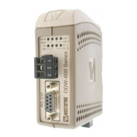
RS-232 (DCE)
1
2
3
4
5
6
7
8
9
Position Product marking
RJ-11C
Screw
terminal**
Direction* Description RJ-11C Screw terminal
a – Not Connected
b In/Out PSTN Transmit/ Receive
Disconnects from “pin c”
when the modem goes
Off-Hook
c No. 2 In/Out PSTN Transmit/ Receive
d No. 1 In/Out PSTN Transmit/ Receive
e In/Out PSTN Transmit/ Receive
Disconnects from “pin c”
when the modem goes
Off-Hook
f – Not Connected
* Direction relative to this unit. ** The PSTN screw terminals are shared with 2-wire Leased Line.
PSTN
LL2
LL1
Position Direction Description Product marking
No. 1 In/Out 2-wire Receive/ Transmit LL1
No. 2 In/Out 2-wire Receive/ Transmit LL2


 To Next Page