EasyManua.ls Logo

Westinghouse WGen5300c - User Manual

Westinghouse WGen5300c
30 pages
Print Icon
To Next Page IconTo Next Page
Loading...
USER MANUAL
DO NOT RETURN THIS PRODUCT TO THE STORE
If you have questions or need assistance, please call customer
service at 855-944-3571.
WGen5300c
Portable Generator
Gasoline: 5300 Running Watts | 6600 Peak Watts
Question and Answer IconNeed help?

Do you have a question about the Westinghouse WGen5300c and is the answer not in the manual?

Summary

Introduction

Disclaimers

Legal statements and rights reserved regarding manual content and specifications.

All Rights Reserved

Statement regarding intellectual property and reproduction rights.

Specifications

Notice

Important operating conditions and environmental factors affecting generator performance.

Product Registration

Information on how to register the generator for warranty coverage.

Safety

Safety Definitions

Explains the meaning of safety alert words like DANGER, WARNING, CAUTION, and NOTICE.

Safety Symbols

Lists and describes the various safety symbols used in the manual and on the generator.

Safety Instructions

Correct Use

Guidelines for the proper placement and usage of the generator to minimize risks.

Incorrect Use

Lists locations where the generator should not be operated due to safety hazards.

General Safety Precautions

Fuel Safety

Precautions for handling and storing gasoline safely to prevent fires and explosions.

Safety Labels

Generator Safety Labels

Visual identification and explanation of key safety labels affixed to the generator unit.

CO Sensor

Control Panel CO Auto-Shutoff

Explains the function and indicators of the carbon monoxide detection system.

Action Label

Provides instructions for immediate action in case of automatic shut-off due to CO detection.

Components

Control Panel Components

Identifies and describes the various controls and indicators on the generator's control panel.

Data Center

Details the functions of the Data Center display for monitoring generator status and maintenance.

Generator Components

Fuel System Components

Identifies key components related to the fuel system, including the tank, valve, and gauge.

Engine Components

Identifies external engine parts like spark plug, carburetor, and muffler/spark arrestor.

Assembly

Carton Contents

Lists all items included in the generator packaging.

Install Feet and Wheels

Step-by-step instructions for attaching the mounting feet and wheels to the generator.

Initial Oil Fill

Recommended Engine Oil Type

Chart showing recommended engine oil types based on ambient temperature.

Fuel

Fuel Requirements

Specifies the type of gasoline and ethanol content suitable for the generator.

Using Fuel Stabilizer

Filling the Fuel Tank

Notice

Important notes on fuel tank filling and avoiding contamination.

Operation

Generator Location

Critical safety guidance on where to place the generator for ventilation and hazard avoidance.

Grounding

Information on generator grounding requirements and potential hazards.

Voltage Selector Switch

Break-in Period

Guidelines for the initial engine break-in period to ensure longevity.

Before Starting the Generator

Pre-start checks and verifications required before operating the generator.

Starting the Engine

Step-by-step instructions for starting the generator using electric or recoil methods.

Generator Capacity

Power Management

Strategy for connecting loads sequentially to protect the generator and connected devices.

Wattage Reference

A guide listing typical wattage requirements for various tools and appliances.

Extension Cords

Extension Cord Sizing

Table providing recommended gauge sizes for extension cords based on amperage and length.

Transporting

Caution

Safety precautions and steps to follow before and during generator transport.

Maintenance

Maintenance Schedule

Recommended maintenance tasks based on operating hours or calendar intervals.

Maintenance Replacement Parts

List of common replacement parts and their part numbers.

Air Filter Maintenance

Instructions for inspecting, cleaning, and replacing the air filter.

Engine Oil Level Check

Recommended Engine Oil Type

Chart showing recommended engine oil types based on ambient temperature.

Engine Oil Change

Maximum Oil Capacity

Specifies the total engine oil capacity for the generator.

Spark Plug Maintenance

Spark Plug Gap

Specifies the correct electrode gap for the spark plug.

Spark Arrestor Service

Battery Maintenance

Charging a Dry Location

Instructions for charging the generator battery using the included charger.

Battery Replacement

Storage

Short Term Storage

Procedures for storing the generator for periods up to six months.

Long Term Storage

Procedures for storing the generator for periods longer than six months.

Draining the Fuel Tank

Fuel Valve Maintenance

Valve Clearance

Valve Clearance Specifications

Table detailing intake and exhaust valve clearance specifications and torque values.

Troubleshooting

Engine Will Not Start

Lists common causes and corrections for the engine failing to start.

Engine Starts, Then Shuts Down

Identifies reasons for the engine shutting down shortly after starting and their solutions.

Engine Lacks Power

Explains causes for reduced engine power and how to resolve them.

Exploded Views and Parts List

Engine Exploded View

Diagram showing the assembly of engine components with numbered parts.

Engine Parts List

Crankcase Assembly

List of parts related to the generator's crankcase.

Cylinder Head Assembly

List of parts associated with the engine's cylinder head.

Piston & Piston Ring Assembly

List of parts for the piston and piston ring assembly.

Engine Parts List Continued

Flywheel Assembly

List of parts constituting the flywheel assembly.

Recoil Starter Assembly

List of parts for the recoil starter mechanism.

Generator Exploded View

Generator Parts List

Frame Assembly

List of parts related to the generator's main frame structure.

Battery Assembly

List of parts associated with the generator's battery system.

Control Panel Assembly

List of parts comprising the generator's control panel.

Generator Parts List Continued

Alternator Assembly

List of parts for the generator's alternator.

CO Module Assembly

List of parts for the carbon monoxide sensor module.

Schematics

Control Panel Schematic

Wiring diagram for the generator's control panel and associated components.

Engine and Alternator Schematic

Wiring diagram illustrating the engine, starter, battery, and alternator connections.

Overview

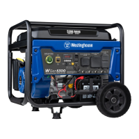
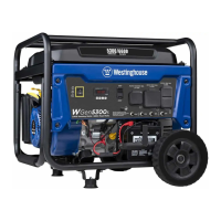
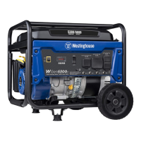
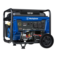
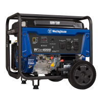
This document is a user manual for the Westinghouse WGen5300c Portable Generator, a gasoline-powered device designed to provide electrical power. It offers 5300 running watts and 6600 peak watts, making it suitable for a variety of applications, from powering essential home appliances during outages to providing electricity for tools at a job site.

Function Description

The WGen5300c Portable Generator is engineered to convert the mechanical energy from a gasoline engine into electrical energy, providing both 120V and 240V AC output. Its primary function is to serve as a reliable backup power source or a portable power solution in locations where grid electricity is unavailable. The generator features a robust engine that drives an alternator to produce electricity. A key safety feature is the integrated CO Sensor, which monitors for the accumulation of poisonous carbon monoxide gas around the generator. If increasing levels of CO are detected, the sensor automatically shuts down the engine to prevent potential harm, providing a crucial layer of protection for users. The generator's control panel includes various outlets, circuit breakers, and indicators to manage power output and monitor operational status.

Usage Features

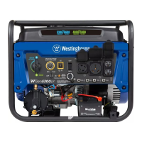
The WGen5300c is designed for ease of use with several convenient features. It offers a Push-Button Electric Start for quick and effortless engine ignition, eliminating the need for manual recoil starting in most situations. A Battery Switch allows users to turn the battery ON or OFF, which is essential for electric or remote starting. The Data Center on the control panel provides real-time operational information, allowing users to toggle through displays for voltage, frequency (Hz), total lifetime run hours, and a run/maintenance timer. This helps users keep track of the generator's usage and anticipate maintenance needs.

For power output, the generator is equipped with multiple receptacles:

  • 120/240 Volt AC, 30 Amp NEMA L14-30R Twist-Lock Receptacle: Capable of supplying a maximum of 30 Amps, suitable for larger appliances or transfer switches.
  • 120 Volt AC, 30 Amp NEMA TT-30R Receptacle: Also providing up to 30 Amps, commonly used for RVs.
  • 120 Volt AC, 20 Amp Duplex NEMA 5-20R Receptacles: Standard household outlets, each capable of supplying up to 20 Amps.

A Voltage Selector Switch allows users to choose between 120 Volts or 240 Volts output, providing flexibility for different power requirements. It is crucial to shut off the generator before switching voltages. The generator also includes AC Circuit Breakers (20 Amp and 30 Amp) that automatically switch OFF in case of a short circuit or significant overload, protecting both the generator and connected devices. A Ground Terminal is provided for external grounding, which may be required depending on local electrical codes and usage methods.

The Smart Switch Outlet allows connection to a Westinghouse ST Switch (sold separately), potentially enabling remote control or automatic transfer capabilities. A Battery Charging Port is included for charging the generator's battery with the provided charger, and a Battery Indicator illuminates when power is ON.

For safe operation, the manual emphasizes using the generator OUTSIDE and far away from windows, doors, and vents to prevent carbon monoxide poisoning. It also provides guidance on Power Management, advising users to add electrical loads sequentially to prolong the life of the generator and attached devices. The Break-In Period instructions recommend not exceeding 50% of the rated running watts for the first five hours and varying the load to help seat the piston rings.

Maintenance Features

The WGen5300c is designed with several features to facilitate regular maintenance and ensure longevity. The Data Center not only displays run hours but also includes a Run Time/Maintenance Timer that shows current run time and displays maintenance reminders when required. These reminders are linked to specific Maintenance Codes (e.g., P25 for changing engine oil, P50 for cleaning the air filter, P100 for fuel valve maintenance and valve clearance inspection). These codes help users follow a structured maintenance schedule based on unit lifetime hours.

Key maintenance procedures outlined in the manual include:

  • Initial Oil Fill and Engine Oil Level Check: Instructions are provided for adding the correct type and amount of oil (SAE 10W-30 recommended) and checking the oil level using the dipstick.
  • Engine Oil Change: Detailed steps for draining old oil and refilling with new oil, with a recommendation for a new oil drain plug crush washer at each change.
  • Air Filter Maintenance: Instructions for cleaning the air filter every 50 hours or six months, with increased frequency recommended in dusty environments.
  • Spark Plug Maintenance: Guidance on inspecting, cleaning, and replacing the spark plug, including checking the electrode gap.
  • Spark Arrestor Service: Steps for cleaning the spark arrestor screen to maintain engine performance.
  • Fuel Valve Maintenance: Procedures for cleaning the fuel sediment cup, screen, and o-ring.
  • Battery Maintenance and Replacement: Information on charging the battery with the included trickle charger and steps for replacing the battery when necessary.
  • Storage Preparation: Recommendations for short-term and long-term storage, including adding fuel stabilizer, draining the carburetor float bowl, and draining the fuel tank to prevent fuel deterioration and corrosion.

The manual also provides a Maintenance Schedule with hourly and calendar intervals for various tasks, emphasizing that more frequent service may be required under adverse operating conditions. It also lists Maintenance Replacement Parts with their corresponding part numbers for easy ordering.

Westinghouse WGen5300c Specifications

General IconGeneral
Power Output (Peak/Starting)5300 Watts
Engine Type4-Stroke OHV
Fuel TypeGasoline
Run Time at 50% Load10 Hours
Voltage120/240 V
Frequency60 Hz
Noise Level68 dBA
Fuel Tank Capacity4.0 Gallons
Run Time at 25% Load14 Hours
Starting MethodRecoil Start
Wheel KitIncluded

Related product manuals