INSTALLATION INSTRUCTIONS
Installing the WF-8700 Series Power Center
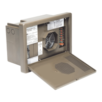
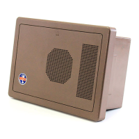
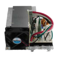
Mounting the Enclosure
e WF-8700 Series enclosure should be mounted in an accessible area such as a wall or in the
side of a cabinet. e front of the enclosure should not be obstructed to allow free air ow for
the cooling fan. NOTE: e WF-8712P does not have a fan. e enclosures will slide into rough
openings as follows:
• WF-8712P and WF-8725P – 10 7/16” W x 6 1/8” H x 3 ¾” D
• WF-8725P and WF-8735P – 10 3/8” W x 6 7/8” H x 4 5/16” D
Aer wiring is completed, the enclosure fastens to the wall or cabinet using 4 wood screws (not
supplied).
Wiring the AC Breakers
Make sure no AC power is coming into the RV from either the Shore Power cord or an on-
board generator. Determine the proper size breakers for the loads the WF-8700 Series Power
Center will be powering. You can use either single or duplex breakers, or a combination of both.
We recommend that all the breakers used be of the same brand. A total of 4 breakers can be
mounted in the WF-8712P and WF-8725P when using duplex breakers: 1 Main breaker and up
to 3 Branch breakers. A total of 6 breakers can be mounted in the WF-8735P and 8740P when
using duplex breakers: 1 Main and up to 5 Branch breakers. Refer to the tables on pages 5 and 6
for a selection of approved breakers. e Main breaker should be 30 Amp and is to be installed
in the le-most position. See the wiring diagrams below. A hold down clip is provided to keep
the breaker securely in place.
e 30 Amp power cord is routed through the large knockout in the back of the wiring
compartment and secured with a Romex clamp. e Black (Hot) wire is connected to the 30
Amp Main breaker as shown. e White (Neutral) wire is connected to the Neutral Terminal bar
at the bottom of the wiring compartment. e Green (Ground) wire is connected to the Ground
Terminal bar also located at the bottom of the compartment.
Route the Romex leads for the Branch circuits through the Strain Reliefs in the back of the
wiring compartment. In a similar fashion, connect the Black wire to the Branch breaker and the
White and Green wires to the appropriate Terminal bar.
e Black power wire for converter power on the WF-8735P and WF-8740P has a pigtail
connection. e metal pin is inserted in the Branch breaker designated for converter power.
e end with the wire nut can be used to power another circuit if necessary. If not used, leave
the wire nut installed and push the wire to the side. Make sure all terminals are torqued to the
specications listed on the back of the door assembly.
10
 Loading...