P82467-001 F
Sheet 5 of 6
CAUTION: If sheated multiconductor cable or 3/4" conduit fittings are used, check that installed product has sufficient clearance
and wiring room prior to installing backboxes and conduit.
1. Multitone Appliances can be flush mounted to a standard 4 inch square by 2-1/8 inch deep electrical box (Figure A) or a standard
2-gang by 2-1/2 inch minimum deep electrical box (Figure B).
2. Select largest backbox shown in Mounting Options where possible, to provide additional wiring room for easy installation.
3. Conduit entrance to backboxes should be selected to insure sufficient wiring clearance for installed equipment. When extension
rings are required, conduit should enter through backbox, not extension ring. Use Steel City #53151/1-1/2" deep or #53171/2-1/8"
deep extension rings or equal with same area cut out in back.
4. The MT-12/24 model can also be surface mounted to Wheelock's Indoor/Outdoor Backbox (Model IOB) for indoor/outdoor use
(Figure C). The IOB is NOT
intended for use with the MT4-12/24.
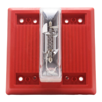
5. The MT-12/24 model is supplied with four snap-in covers to hide the mounting holes and provide an attractive installation. The
snap-in covers are interchangeable and have slots on each end so they can be removed if necessary (by prying them up with a thin
blade screwdriver). To insert snap-in cover, slide one side partially into mounting hole recess; align the cover so that snap-in
cover and grille are parallel to each other (not tilted) and snap cover into place.
6. The IOB surface backbox has 1/2 inch conduit knockouts on two sides. It has a variety of knockouts on the back for mounting it
to recessed electrical boxes and for wire entrances (Figure D). It can also be mounted to a surface with the two mounting ears that
are supplied. The ears slide into slots on the back of the box. Use appropriate anchors for the wood screws that are supplied with
the box (if necessary).
7. For outdoor use, the IOB includes a prefastened gasket and four hole plugs. Make sure the condensation drain holes on the box
face down and that the box is vertical to permit drainage of any moisture. Use the mounting ears to secure the box (do not use the
back knockouts). Use the hole plugs to seal the unused mounting holes on the Multitone grille (press them in securely from the
back side of the grille). Mount the unit to the IOB with the four #8-18 screws supplied with the box.
8. The Code 3 Horn and Code 3 Tone incorporate the temporal pattern specified by ANSI/NFPA/ISO for standard emergency
evacuation signaling. They should be used only for fire evacuation signaling and not for any other purpose.
9. The Horn and Bell Tones can be used on coded systems with a minimum On-Time of 1/4 second. All other tones are
recommended for use only on continuous (non-coded) systems.
The Multitone products and these instructions are copyrighted by Wheelock and contain proprietary, confidential and trade secrets of
Wheelock. No part of the Multitone products and these instructions may be photocopied, printed or reproduced in any form or
modified, adapted, changed or enhanced, or converted to another programming language, or used to create updated, related or
derivative works, without the prior written consent of Wheelock. No part of the Multitone shall be decompiled, disassembled or
reverse engineered.
NOTE: This equipment has been tested and found to comply with the limits for a Class B digital device, pursuant to Part 15 of the
FCC Rules. These limits are designed to provide reasonable protection against harmful interference in residential installation. This
equipment generates, uses and can radiate radio frequency energy and, if not installed and used in accordance with the instructions,
may cause harmful interference to radio communications. However, there is no guarantee that interference will not occur in a
particular installation. If this equipment does cause harmful interference to radio or television reception, which can be determined by
turning the equipment off and on, the user is encouraged to try to correct the interference by one or more of the following measures:
1) Reorient or relocate the receiving antenna, 2) Increase the separation between the equipment and receiver, 3) Connect the
equipment into an outlet on a circuit different from that to which the receiver is connected, and 4) Consult the dealer or an
experienced radio/TV technician for help.
ANY MATERIAL EXTRAPOLATED FROM THIS DOCUMENT OR FROM WHEELOCK MANUALS OR OTHER
DOCUMENTS DESCRIBING THE PRODUCT FOR USE IN PROMOTIONAL OR ADVERTISING CLAIMS, OR FOR
ANY OTHER USE, INCLUDING DESCRIPTION OF THE PRODUCT'S APPLICATION, OPERATION, INSTALLATION
AND TESTING IS USED AT THE SOLE RISK OF THE USER AND WHEELOCK WILL NOT HAVE ANY LIABILITY
FOR SUCH USE.
IMPORTANT: READ SEPARATE "GENERAL INFORMATION" SHEET FOR INFORMATION ON THE
PLACEMENT, LIMITATIONS, INSTALLATION, FINAL CHECKOUT AND PERIODIC TESTING OF NOTIFICATION
APPLIANCES.
Limited Warranty
Wheelock products must be used within their published specifications and must be PROPERLY specified, applied, installed, operated,
maintained and operationally tested in accordance with these instructions at the time of installation and at least twice a year or more
 Loading...