Page 2
Specifications:
Input Voltage . . . . . . . . . . . . . . 12.8 VDC ±20% - Negative Ground Only
Main Input Current . . . . . . . . . . . . . . . . . . . . . . . . . . . . . . 70 Amps Max.
Siren Input Fuse . . . . . . . . . . . . . . . . . . . . . . . . . . . . . . . . . . . . 15 Amps
Stand-by Current (no ignition) . . . . . . . . . . . . . . . . . . . . . . . . . . . . 1 mA
Operating Temperature. . . . . . . . . . . . . . . . . . . . . . . . . . -30°C to +60°C
Storage Temperature . . . . . . . . . . . . . . . . . . . . . . . . . . . -40°C to +70°C
Humidity. . . . . . . . . . . . . . . . . . . . . . . . . . . . . . . . 99% (Non-condensing)
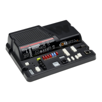
Siren Amplifier Module Module
Standard Audio Bandwidth @25 Watts . . . . . . . . 300 to 10000 Hz ±3db
Distortion @25Watts . . . . . . . . . . . . . . . . . . . . . . . . . . . . . . 1% Maximum
Output Voltage @15VDC @11 ohms . . . . . . . . . . . . ...24Vrms Maximum
Speaker Impedance. . . . . . . . . . . . . . . . . . . . . . . . . . . 11 Ohms Minimum
Howler Audio Bandwidth @25 Watts. . . . . . . . . . . . . . . . 200-10000 Hz
High Current Outputs
4 High Current Outputs: . 2 - 15 Amps Max. 2 - 10 Amps Max. (internally
limited)
NOTE: Total current of High Current Outlets not to exceed 60 Amps
1 Dry Contact Relay: 15 Amp (Fused)
Low Current Outputs
12 Low Current Outputs . . . . . . . . . . . . . 2 Amps Max (internally limited)
6 Digital Inputs / 4 Analog Inputs / 1 Ignition Sense
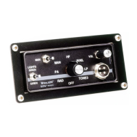
Installation:
This siren is designed to be mounted directly onto the dash or other sur-
face through the use of a bail strap mounting bracket. The unit may also
be mounted into your vehicle’s console (if so equipped).
Bail Mount:
1. Locate a suitable mounting location.
2. Position bail strap in selected mounting location and drill mounting
holes, then secure the bail strap to the vehicle.
3. Secure the siren to the bail strap using the included hardware.
Console Mount:
1. Console manufacturers offer mounting kits that include all the
necessary hardware and brackets to mount this unit into their console.
The console mount brackets are secured onto the unit in the same way.
Please refer to the manual included with your console.
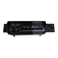
Remote Mounting Solution:
1. Install the two remote mounting brackets using the included hardware.
2. Position and install the Core-S™ / Remote Mounting bracket assembly
and secure it with the included four mounting screws.
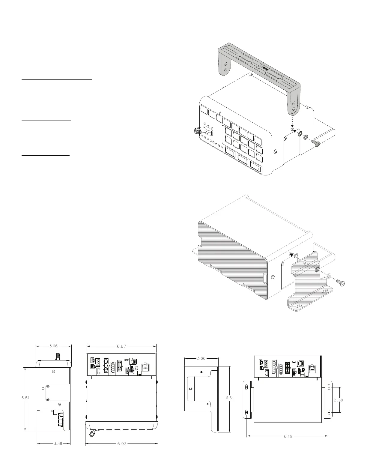
Dimensions:
Bail Mount:
Remote Mounting Solution:
 Loading...