Page 3
Wiring:
All customer supplied wires that connect to the positive terminal of
the battery must be sized to supply at least 125% of the maximum
operating current and FUSED
at the battery to carry that load. DO
NOT USE CIRCUIT BREAKERS WITH THIS PRODUCT!
Main Power (J16):
1. Locate the connector with RED & BLK wires, sized to fit into the system
power connectors (included).
2. Route the two RED 10 AWG wires (included) from the Core-S™ module
to an unused circuit fused @ 40 Amps each wire (the fuse panel, for
example). Do not connect to this circuit yet.
3. Route the BLACK 10 AWG wire (included) from the Core-S™ module to
the vehicle’s chassis ground typically adjacent to the battery.
4. Complete the connections and plug the connectors into the Core-S™
Module.
Programmable Inputs:
There are 6 digital and 4 Analog programmable inputs in the Core-S™
system.
Digital Inputs (J9) (Pins 1-6)
These digital inputs can be configured to detect either a positive or ground
activated signal.
Analog Inputs and Ignition Sense(J9)
Analog Inputs (Pins 7,8,9,10)
These inputs can detect a varying, analog voltage range. The output
signal line from devices such as a K-9 temperature sensor may be
connected to these inputs.
Ignition Sense (Pin 12)
This input should be wired to an ignition signal and controls when the
Core-S™ system turns on (when ignition is detected) and when the
system turns off (when ignition line turns off). The Core-S™ system
turning off can be further configured by programing a Shutdown Delay to
keep the system active after the ignition signal turns off.
Switched Outputs:
Low Current Outputs (J15)
• 2 Amp Active High, internally limited (Pins 1-11)
• 2 Amp Active Low, internally limited (Pin 12)
High Current Outputs (J14)
These outputs can be programmed by the Whelen Command® software
to activate in any combination, they also can be set up to source current at
VBAT.
• 15 Amp Max, internally limited (Pins 1-2,)
• 10 Amp Max, internally limited (Pins 3-4)
Dry Contact Relay (J3) (See “Hands Free Siren”)
• 15 Amp Max, Fused
• Pin 1 is the Normally Open terminal.
• Pin 2 is the relay’s Common terminal.
• Pin 3 is the Normally Closed terminal.
Siren Speaker (J1)
Note: Use the GREY (+) and ORANGE (-) wires when installing a
Howler® speaker.
1. Route the ORANGE, GREY, YELLOW and BROWN 18 AWG wire
(included) from the amp/relay module to the siren speakers.
2. Connect the YELLOW (+) and BROWN (-) wires to speaker one.
3. Connect the GREY (+) and ORANGE (-) wires to speaker two.
Audio signals (J10):
Radio Rebroadcast (Pins 1, 2)
Two blue wires are used to connect the audio output of your two-way radio
to the Whelen Siren Module for radio rebroadcast. (Optional connection).
NOTE: Radio rebroadcast will NOT work with radios requiring
amplified remote speakers! If your remote speaker is amplified (i.e.
contains a power amp circuit in the speaker assembly), the signal
from the radio will not be appropriate for this input.
Locate the two wires that connect the external speaker to the two-way
radio. Splice one of the blue wires into one of the radio’s speaker wires,
then splice the other blue wire into the other radio speaker wire.
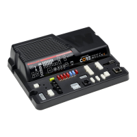
Radio Repeat Volume Adjustment
Locate the Radio Repeat adjustment potentiometer on the left side of the
Core module. Set the volume of the vehicle’s two-way radio to its normal
operating level. Press the RAD button on the control head to activate
Radio Repeat. As incoming transmissions are received, adjust the Radio
Repeat potentiometer to set the desired level. Turn the potentiometer
clockwise to increase and counter-clockwise to decrease the level.
Auxiliary Audio Input (Pins 4,5)
Two green wires are proved to connect the auxiliary audio output of an
appropriate Whelen device to this unit.
Cabin Speaker (Pins 3,6)
The yellow wire goes to the positive (+) speaker terminal, and the white-
yellow wire goes to the negative (-) speaker terminal.
Note: Recommended cabin speaker is 5 Watts at 8 Ohm.
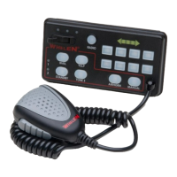
Microphone (J11):
Attach the microphone extension cable to this connector, route the cable
to the desired location in the vehicle and secure the other end to a fixed
location and then attach the microphone.
PA Volume Adjustment
To adjust the PA volume refer to the WeCan® Whelen Command®
software.
USB-C Programming Port (J7):
Attach to computer using USB-C cable when programming the system
with the Whelen Command® Software.
NOTE: Charging-only Cables
from multiple mobile devices (i.e. cell phones or tablets) are not
recommended for data transfer use. Not all cables are capable of
charging and data transfer.
Ethernet Port (J2):
To be used with a Whelen Ethernet device.
CAN Communications (J8,J4):
J8 is the control link between all WeCanX® devices. Core-S™ ties into the
vehicles OBDII port using J4.
 Loading...