J10--1 BLU - RADIO (+)
2 - - (-)BLU RADIOJ15-
3 - (+)WHT/YEL CAB SPKRJ15-
4 - (+)GRN - AUX INJ15-
5 - (-)GRN - AUX INJ15-
6 - YEL - (-)CAB SPKRJ15-
- 1 BRN - Normally OpenJ3 -
2 - RED - Common
3 - ORG - Normally ClosedJ17 -
J14 - 1 - BRN - HC Output 1
2 - RED - HC Output 2J17 -
3 - ORG - HC Output 3J17 -
4 - YEL - HC Output 4J17 -
- 1 - BRN - LC Output 1J15
2 - RED - LC Output 2J14 -
3 - ORG - LC Output 3J14 -
4 - YEL - LC Output 4J14 -
5 - GRN - LC Output 5J14 -
6 - BLU - LC Output 6J14 -
7 - VIO - LC Output 7
8 - GRY - LC Output 8J14 -
9 - WHT/BRN - LC Output 9J14 -
10 - WHT/RED - LC Output 10J14 -
11 - WHT/ORG - LC Output 11J14 -
12 - WHT/YEL - LC Output 12J14 -
- 1 - WHT/BRN - Dig. Input 1J9
2 - WHT/RED - Dig. Input 2J14 -
3 - WHT/ORG - Dig. Input 3J14 -
4 - WHT/YEL - Dig. Input 4J14 -
5 - WHT/GRN - Dig. Input 5J14 -
6 - WHT/BLU - Dig. Input 6J14 -
7 - BRN - Analog Input 1
8 - RED - Analog Input 2J10 -
9 - ORG - Analog Input 3J10 -
10 - YEL- Analog Input 4J10 -
11 - N/AJ10 -
12 - RED/WHT - IgnitionJ10 -
This worksheet has been provided
so that a written record of all Input,
Output and Axillary connections may
be created. After all data has been
verified and recorded, store and
retain this sheet for future reference.
It is recommended that you make a
copy of this worksheet before filling in.
so that if any changes need to be
made you will have a blank copy.
CONNECTOR - PIN FUNCTION- ASSIGNED TO:
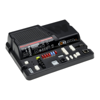
Cencom™ Core-S™
Installation Worksheet
 Loading...