28
Item
No.
Parts Description
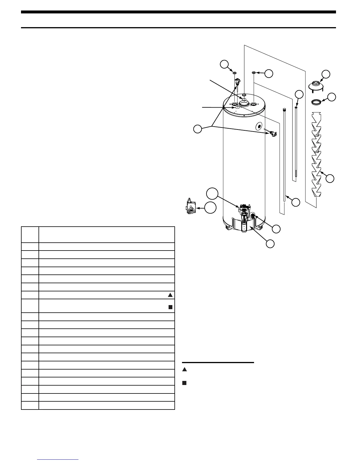
1 DRAFT HOOD
2 REDUCER RING - SOME MODELS
3 FLUE BAFFLE
4 HEAT TRAP (COLD) - SOME MODELS
5 HEAT TRAP (HOT) - SOME MODELS
6 COLD WATER DIP TUBE
7 ANODE ROD
8 TEMPERATURE & PRESSURE RELIEF VALVE (LOCATED
TOP OR SIDE)
9 DRAIN VALVE
10A GAS CONTROL VALVE/THERMOSTAT
10B GAS CONTROL VALVE/THERMOSTAT
11 OUTER DOOR
12* PILOT ASSEMBLY (Natural Gas)
13* BURNER DOOR ASSEMBLY (Natural Gas/Low Nox)
14* TWO PIECE WIRE CONNECTOR WITH RETAINER CLIP
15* BURNER DOOR GASKET
16* VIEWPORT ASSEMBLY
17* THERMOCOUPLE
18* PIEZOELECTRIC IGNITER BUTTON
19* FLEXIBLE MANIFOLD TUBE
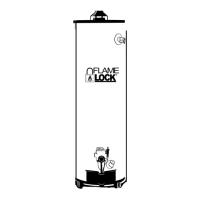
REPAIR PARTS ILLUSTRATION
When ordering repair parts always give the following
information:
1. Model, serial, and product number
2. Type of gas
3. Item number
4. Parts description
Repair Parts List
LEGEND
Special anode rod (see “Anode Rod/Water Odor”
section)
Temperature and Pressure Relief Valve is required, but
may not be factory installed
*Pictured on next page.
11
9
7
6
1
2
3
8
5
4
Alternate anode
location for top
T&P
Anode location
for side T&P
10A
10B