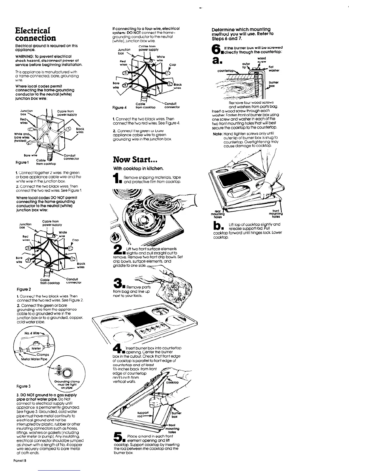
Electrical
connection
ElectrIcal
ground
Is required on this
opplionce.
WARNING: To prevent eleclricol
shock hazard. disconnect Dower ot
This appliance IS manufactured with
a frame-connected, bare. grounding
wire
Where local codes permit
connecting the frame-grounding
conduclor lo the neutral (while]
Junction box wife:
I. Connect together 2 wires: the green
or bare appliance cable wbre and the
white wire in the junction box.
2. Connect the two black wires. Then
connect the two red wares. See Figure 1
Where local codes DO NOT permit
connecting the frame.grounding
conductor to the neutral (while)
junction box wire:
Cable
trom
powe, supply
Figure 2
1. Connect the two black wires. Then
connect the two red wares. See Figure 2.
2. Connect the green or bare
grounding wire from the appliance
cable to a grounded wire in the
junction box or to a grounded. copper.
cold water pipe.
Figure 3
3. DO NOT ground to a gas supply
pipe or hot water pipe. Do
Not
connect to electrlcal supply until
appliance is permanently grounded.
See Frgure 3. Grounded. cold water
pipe must have metal continuity to
electrical ground and not be
interrupted by plastic, rubber or other
Insulating connectors such as hoses,
htMgs, washers or gaskets (Including
water meter or pump]. Any insulating.
electrical connector should be jumped
as shown with a length of No. 4 copper
wire securely clamped to bare metal
at ooth ends.
Panel B
If connecting to 0 four-wire,electrical
system:
DO NOT connect the frame-
grounding conductor to the neutral
(whlte),)unclion box wire.
Cable
horn
JUKllOll
power supply
Figure 4
from cooklop
1. Connect the two black wares. Then
connect the two red wires. See Figure 4
2. Connect the green or bare
appliance cable wire to green
grounding wire in the junction box.
Now Start...
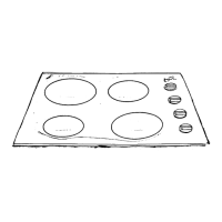
With cooktop in kitchen.
1
Remove shipping materials, tape
n
and protective film from cooktop
remove. Remove two front drip bowls. Set
drip bowls, surface elements. and
griddle to one side.-
‘Insert burner box into countertop
I opening. Center the burner
box in the cutoit. Check that front edge
of cooktop is parallel to front edge of
countertop and at least
Iti-lnches’back from front
edge of countertop
and6inch from
vertical walls.
Place a hand in each front
W element opening
and lifi
cooktop. Support cooktop by inserting
the rod between the cooktoo and the
burner box
Determine which mounting
method you will use. Refer to
Steps 6 and 7.
6
If the burner box will be screwed
wdlrectly through the countertop:
Remove four wood screws
and washers from parts bag.
Insert a wood screw through each
washer, Fasten front of burner box using
one screw and washer in each of the
two front mounting holes that will best
secure the c&top ta the countertop.
Note:
Hand tighten screws only until
outer Ilp of burner box is snug to
countertop Ovetilghtenlng may
cause damage to cooktop.
b.
Lift top of cooktop slightly and
release support rod. Pull
cooktop forward until hinges lock. Lower
cooktop