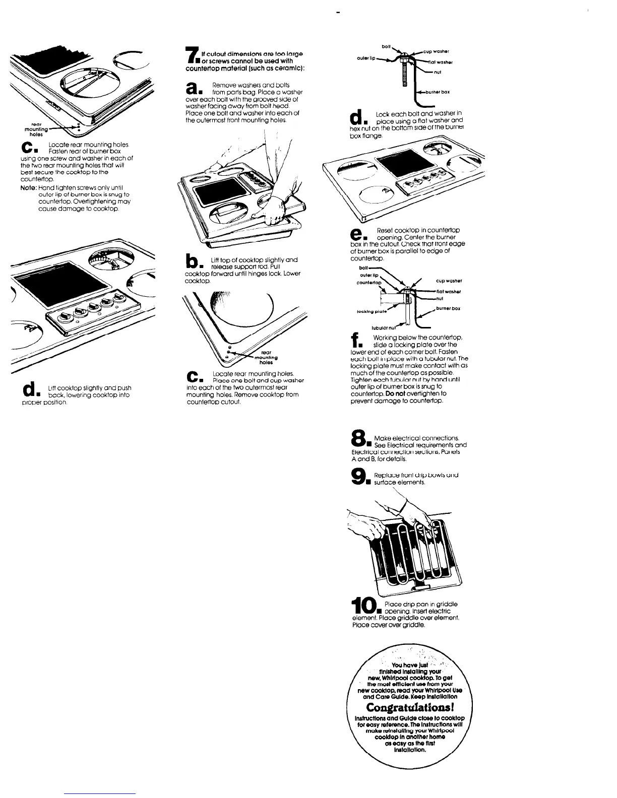
C.
Locate rear mounting holes
Fasten rear of burner box
using one screw and washer in each of
the hue rear mounting holes that will
best secure the cooktop to the
countertop.
Note: Hand tighten screws only until
outer Ilp of burner box is snug to
COuntertOp. OVefliQhtenlnQ may
cause damage to cooktop
7
If cutout dimenslons are too large
W or screws cannot be used with
countertop material (such OS ceramlc):
a.
Remove washers and bolts
from parts bag. Place a washer
over each bolt with the grooved side of
washerfacing away from bolt head
Place one bolt and washer into each of
the outermost front mounting holes
d
Luff cooktop slightly and push
8 back, lowering cooktop into
proper positlon
b
Lifl top of cwktop Slightly and
n
release support red Pull
cooktop forward until hinges lock Lower
cooktop.
c.
Locate rear mounting holes.
Place one bolt and cup washer
Into each of the two outermost rear
mounting holes. Remove cooktop from
countertop cutout.
d
Lock each bolt and washer in
.
place using a flat washer and
hex nut on the bottom side of the burner
e.
Reset cooktop in countertop
opening Center the burner
box in the cutout Check that front edge
of burner box is parallel to edge of
countertop.
f.
Working below the countertop.
slide a IockinQ plate over the
lower end of each corner bolt Fasten
each bolt in olace with a tubular nut. The
&king plate must make contact with as
much of the countertop as possible
Tighten each tubular nut by hand until
outer lip of burner box is SnUQ to
countertop. Do
not
overtighten to
prevent damage to CoUnterfOp.
8
Make electrical connections.
n
See Electrical requirements and
Electrical connection sections. Panels
A and EI, for details.
9
Replace front drip bowls and
n
surface elements.
Place dnp pan I” griddle
I opening. Insert electric
element. Place griddle over element.
Place cover over griddle.
[ Congratditions! 1