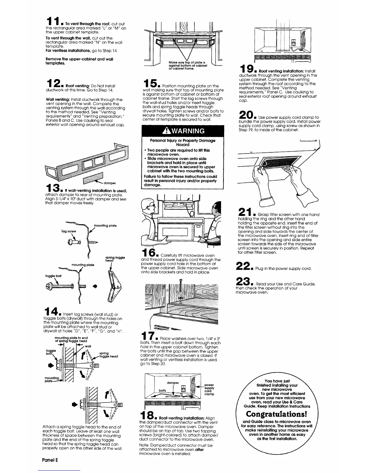
I • To vent through the roof,cut out
4
the rectangulararea marked "L"or "M" on
the upper cabinet template.
To vent through the wall, cut out the
rectangular area marked "N" on the wall
template.
Forventlessinstallations,go to Step 14.
Remove the upper-cabinet and wall
templates.
2 • Roof venting:Do Not install
ductwork at thistime.Go to Step 14.
Wallventing:Installductwork through the
vent opening inthe wall.Complete the
venting system through the wallaccording
to the method needed. See "Venting
requirements"and "Venting preparation,"
Panels B and C. Use caulkingto seal
exteriorwallopening around exhaust cap.
damper
3 • Ifwall-ventinginstallationisused,
attach damper to rearofmounting plate.
Align3-I/4"x 10"duct with damper and see
thatdamper moves freely.
mountingplate
Jagscrew /
spring toggle
head
_=_unt_ng plate
toggle_ _ _IIbolt __,.,_
4 • Insert lag screws (wall stud) or
toggle bolts (drywall) through the holes on
the mounting plate where the mounting
plate will be attached to wall stud or
drywall at holes "D", "E", "F', "G", and "H'.
mounting plateto end
of springtoggle head
-_ _i-- wall
bolt_. If.." Jr f l_.\ sprln.g . .
J'/J "I H l, _,_ hi' toggle neaa
%_n r/. I = _ \_="
.7. _ I | _.\\
L/i
L/i
L//
//
//
/i
//
Attach a spring toggle head to the end of
each toggle bolt. Leave at least one wall
thickness of space between the mounting
plate and the end of the spring toggle
head so that the spring toggle head can
properly open on the other side of the wall.
Panel E
5 • Position mounting plate on the
wall making sure that top of mounting plate
is against bottom of cabinet or bottom of
cabinet frame, Staff the lag screws through
the wall-stud holes and/or insert toggle
bolts and spring toggle heads through
drywall holes. Tighten screws and/or bolts to
secure mounting plate to wall. Check that
center of template is secured to wall.
i I
i I L J
1 _ • Rootventing installation: Install
duotwork through the vent opening in the
upper cabinet. Complete the venting
system through the roof according to the
method needed. See "Venting
requirements," Panel C. Use caulking to
seal exterior roof opening around exhaust
cap.
Personal Injury or Property Damage
Hazard
• Two people are required to lift this
microwave oven.
• Slide microwave oven onto side
brackets and hold in place until
microwave oven is secured to upper
cabinet with the two mounting bolts.
Failure to follow these instructions could
result in personal injury and/or property
damage.
II
6 • Carefully lift microwave oven
and thread power supply cord through the
power supply cord hole in the bottom of
the upper cabinet. Slide microwave oven
onto side brackets and hold in place.
? • Place washers over two, 1/4" x 3"
bolts. Then insert a bolt down through each
hole in the upper cabinet bottom. Tighten
the bolts until the gap between the upper
cabinet and microwave oven is closed. If
wall venting or ventless installation is used,
go to Step 20.
0i Use power supply cord clamp to
bundle the power supply cord. Install power
supply cord clamp, using screw as shown in
Step 19,to inside of the cabinet.
4 • Grasp filter screen with one hand
holding the ring and the other hand
holding the opposite end. Insert the end of
the filter screen without ring into the
opening and slide towards the center of
the microwave oven. Insert ring end of filter
screen into the opening and slide entire
screen towards the side of the microwave
until screen is securely in position. Repeat
for other filter screen.
2 • Plug in the power supply cord.
3 • Read your Use and Care Guide,
then check the operation of your
microwave oven.
_,=A,****.,._.=..._T=___I "damper_" _
powe r
-- supply
cord
clamp
8 • Roof-ventinginstallation:Align
the damper/duct connector withthe vent
on top ofthe microwave oven. Damper
should be on top of tab.Use two tapping
screws (bright-colored)to attach damper/
duct connector to the microwave oven.
Note: Damper/duct connector must be
attached to microwave oven after
microwave oven is installed.
 Loading...