EasyManua.ls Logo

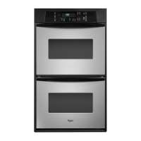
Whirlpool RBD245PD User Manual

Whirlpool RBD245PD
59 pages
To Next Page IconTo Next Page
Page #1 background imageLoading...
Page #1 background image
CONSUMER SERVICES TECHNICAL
EDUCATION GROUP PRESENTS
KR-30
JOB AID
Part No. 8178007
ELECTRIC
BUILT-IN
DOUBLE OVEN

Table of Contents

Other manuals for Whirlpool RBD245PD

Question and Answer IconNeed help?

Do you have a question about the Whirlpool RBD245PD and is the answer not in the manual?

Whirlpool RBD245PD Specifications

General IconGeneral
Oven Capacity4.3 cu. ft.
Oven TypeElectric
Fuel TypeElectric
Self-CleaningYes
ConvectionYes
Interior LightYes
Capacity4.3 cu. ft.
Number of Oven Racks2
ColorBlack
Width30 inches

Summary

FORWARD

GOALS AND OBJECTIVES

The goal is to provide detailed information for proper diagnosis and repair of the Whirlpool Electric Built-In Double Oven.

IMPORTANT SAFETY INFORMATION

SPECIFICATIONS

INSTALLATION HIGHLIGHTS

Electrical Supply Requirements

Essential guidelines and warnings for connecting the appliance to the electrical supply.

REMOVING & REINSTALLING THE OVEN DOOR

Personal Injury Hazard

Safety warnings related to handling the oven door to prevent injury or product damage.

THE OVEN SHUTDOWN THERMAL FUSE & CONTROL PANEL THERMAL FUSE

Oven Shutdown Thermal Fuse

Details on the location and function of thermal fuses that protect the oven from overheating.

Control Panel Thermal Fuse

Information on the thermal fuse protecting the electronic control panel from excessive temperature.

THE OVEN DOOR LATCH ASSEMBLY

HOW THE SELF-CLEAN CYCLE WORKS

COMPONENT ACCESS

REMOVING THE THERMAL FUSE, THE OVEN CONTROL/DISPLAY BOARDS, AND THE TOUCH PANEL ASSEMBLY

Removing Oven Control/Display Boards

Step-by-step instructions for removing the oven's electronic control and display modules.

REMOVING THE POWER SUPPLY WIRING TERMINAL BLOCK AND THE UPPER & LOWER BLOWER MOTORS

REMOVING THE UPPER & LOWER OVEN DOOR LATCH ASSEMBLY

REMOVING AN OVEN LIGHT & AN OVEN TEMPERATURE SENSOR

REMOVING A BROIL ELEMENT

REMOVING A BAKE ELEMENT

REMOVING AN OVEN SHUTDOWN THERMAL FUSE

REMOVING THE CONVECTION FAN MOTOR ASSEMBLY

Electrical Shock Hazard

Mandatory safety instruction: disconnect power before removing the convection fan motor.

REMOVING THE OVEN DOOR GLASS, HINGES, & HANDLE

COMPONENT TESTING

General Testing Precautions

Guidance on performing component tests, including tool requirements and connection checks.

DIAGNOSIS & TROUBLESHOOTING

Electrostatic Discharge (ESD) Sensitive Electronics

Guidance on preventing ESD damage to electronic components.

FAILURE/ERROR DISPLAY CODES

Error Codes and Repair Procedures (Tech Sheets 4451887C & 4451888A)

Table listing fault codes, explanations, and recommended repair steps for specific tech sheets.

Error Codes and Repair Procedures (Tech Sheet 4452022A)

Table listing fault codes, explanations, and repair steps for Tech Sheet 4452022A.

RELAY LOGIC CHART

CONTROL PANEL TEST LOCATIONS

WIRING DIAGRAMS AND STRIP CIRCUITS

Schematic Diagram 1 (Tech Sheet 4451887C)

Detailed wiring schematic for models covered by Tech Sheet 4451887C.

Schematic Diagram 2 (Tech Sheet 4451888A)

Detailed wiring schematic for models covered by Tech Sheet 4451888A.

Schematic Diagram 3 (Tech Sheet 4452022A)

Detailed wiring schematic for models covered by Tech Sheet 4452022A.

Related product manuals