14
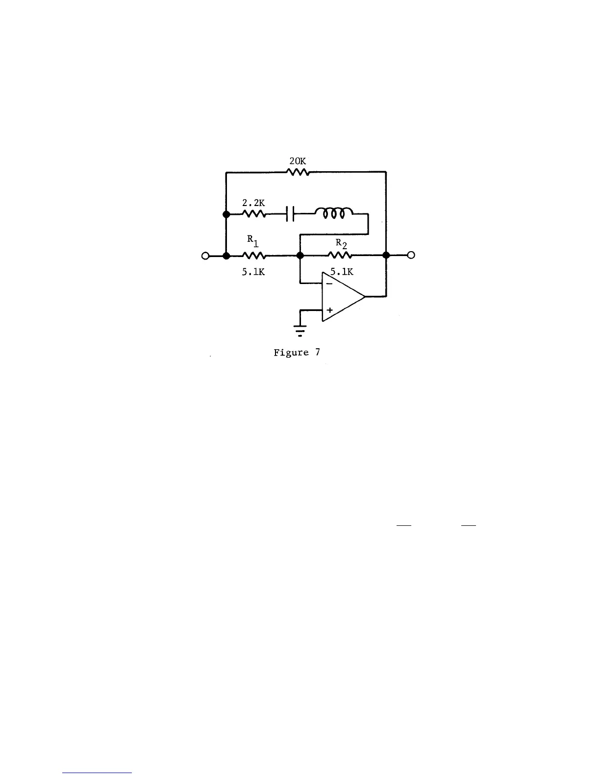
The amplifier summation resistors are equal, and without the filter controls they give a
gain of unity (0 dB). Then if a potentiometer is connected from input to output as shown
below, it has no effect on the gain. Next, the RLC circuit is added. With the pot set at
electrical center, the
RLC
circuit is at a balance position and has no effect on the
response. If it is turned all the way to one end, it looks as follows:
At the resonant frequency of the LC circuit, the 2.2k impedance is in parallel with the
5.1k resistor, and the gain ratio R
2
/R
1
is about 3 to 1, or +10 dB. Par away from f
0
, the
gain returns to unity because L or C is high in impedance and the 2.2k resistance is
effectively out of the circuit. Tuning through f gives a band-pass peak in the response that
may be adjusted to any value from 10 dB down to flat.
Conversely, if the pot is set at the other end, the gain ratio is inverted and the response is
a 10 dB notch. The one octave bandwidth is set by the ratio of
L/C
and is chosen to give
a proper addition of adjacent channel response curves.
In effect, the individual filter sections combine to make up a single filter whose electrical
response curve is free of unwanted ripple and excessive phase shift. In fact, the Model
4100 can provide extended shelving functions up to +10 dB with no ripple and no
phase
shift between adjacent center frequencies.
The RLC filters are divided into two groups. All filter sections in one group are two
octaves apart. A11 in one group are "stacked" on one operational amplifier. The two
octave separation makes reactive tuning
effects small between the stacked sections.