EasyManua.ls Logo

White Rodgers 1E78-151 User Manual

White Rodgers 1E78-151
2 pages
To Next Page IconTo Next Page
Page #1 background imageLoading...
Page #1 background image
1
( ) Raises temperature setting.
2
( ) Lowers temperature setting.
3
*Time button.
4
*PRGM (program) button.
5
*RUN (program) button. Press RUN to resume program.
6
*HOLD button. Press HOLD to bypass the program. Press
RUN to resume program.
7
FAN switch (ON, AUTO).
8
SYSTEM switch (COOL, OFF, HEAT).
* Programmable models only
THERMOSTAT
FURNACE/AIR HANDLER
TYPICAL TERMINAL DESIGNATIONS
R
H
R
C
W
G
Y
O
B
R-RH
4-M-R5
R-RC-V
W-H-4
G-F
Y-Y6
O
B
REMOVE JUMPER
FOR 2 TRANSFORMER
RC/RH SYSTEMS
ADD JUMPER
FOR HEAT PUMP
APPLICATIONS
NOTE: FOR 2 WIRE HEAT ONLY SYSTEMS CONNECT TO RH AND W
24V POWER (HEATING)
24V POWER (COOLING)
HEATING RELAY
FAN RELAY
REVERSING VALVE
REVERSING VALVE
COOLING RELAY
ONLY REQUIRED FOR HEAT PUMP APPLICAITON
REVERSING VALVE ENERGIZED IN COOL MODE
ONLY REQUIRED FOR HEAT PUMP APPLICAITON
REVERSING VALVE ENERGIZED IN HEAT MODE
Basic Installation
Single Stage Thermostats
1E78-144 Non-Programmable
1E78-151 Programmable
For additional information visit: www.white-rodgers.com
For technical support: 1-888-725-9797
Home Owner Support Hotline: 1-877-978-7828
7am–1am CST Mon–Fri • 7am–4pm CST Sat–Sun
Feed wires through the back of the thermostat base and securely
mount to the wall with supplied screws and anchors.
- Switch Electric/Gas Switch to ELEC for Heat Pump or electric
heat application, leave in Gas for gas and oil applications.
- Clip jumper W903 (programmable models only) to disable
Energy Management Recovery feature that starts heat or cool
earlier than the program time.
- Clip jumper W904 for Celsius Display.
- Clip jumper W905 to produce a longer heating cycle which is
normally for hot water or steam (Hydronic Systems).
Mounting and Jumper Options:
Wiring:
Note: For 2 wire heat only systems connect to RH and W.
Identify each wire attached to the old thermostat using the labels
enclosed with the new thermostat.
• Replacebatterieswhen“Change is displayed.
• “Change indicatesbatterieshavelimited
remaining life.
• Systemwillnotoperatewithdeadbatteries.
CAUTION
!
NOTICE! FREEZE HAZARD
• Thermostat installation and all components of the
system shall conform to NEC code for class II circuits.
• Donotexceedspeciedvoltage.
• Donotshortterminalsongasvalveorprimarycontrol.
•Routeandsecurewirestopreventshortingtoadjacent
terminals
WARNING
!
www.white-rodgers.com
www.emersonclimate.com
PART NO. 37-7532A
1424
Base
Back of
Thermostat Body
RC
ELEC GAS
GRH
YO B
W
W903
W904
W905
Elec/Gas
Switch
Mounting
Hole
Mounting
Hole
Figure 1. Thermostat
NOTE: Earlier models refer to 37-7006 for jumper locations.
Figure 8. Thermostat display,buttons and switches
Figure 1. Thermostat
Figure2.Thethermostatbuttonsandswitches
Question and Answer IconNeed help?

Do you have a question about the White Rodgers 1E78-151 and is the answer not in the manual?

White Rodgers 1E78-151 Specifications

General IconGeneral
DisplayDigital
Stages1 Heat / 1 Cool
Voltage24V
BacklightNo
CompatibilitySingle Stage Heating and Cooling Systems
Battery2 AA batteries (included)

Summary

Basic Installation Single Stage Thermostats

Safety Warnings

Important safety precautions for thermostat installation and operation.

Freeze Hazard Caution

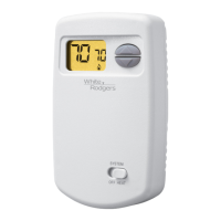
Notice regarding potential freeze hazard and battery status indicators.

Wiring Instructions

Guidance on connecting wires to the thermostat and system.

Thermostat Terminal Designations

Identifies typical terminal designations for thermostat and furnace/air handler connections.

Mounting and Jumper Options

Details on mounting the thermostat and configuring jumper settings.

Electric/Gas Switch Setting

Instructions for setting the Electric/Gas switch for different heating types.

Jumper W903 Function

Disables Energy Management Recovery feature for programmable models.

Jumper W904 Function

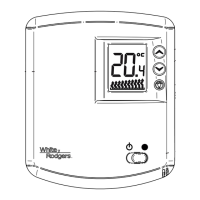
Enables Celsius display mode.

Jumper W905 Function

Produces longer heating cycles for hydronic systems.

Thermostat Buttons and Switches Overview

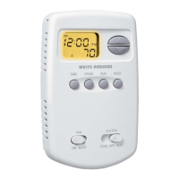
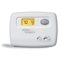
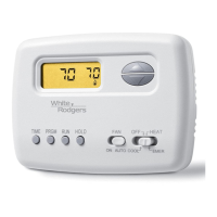
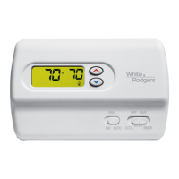
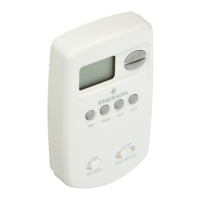
Description of the function of each button and switch on the thermostat.

Thermostat Display Icons and Programming

Thermostat Display Icons

Explanation of various icons displayed on the thermostat screen.

Setting Current Time and Day

Step-by-step guide to setting the current time and day on the thermostat.

Entering Heating Program

Procedure for programming the thermostat's heating periods and temperatures.

Entering Cooling Program

Procedure for programming the thermostat's cooling periods and temperatures.

Display Light Control

Instructions on how to adjust the thermostat's display light.

Checking Programmed Settings

Steps to verify the programmed heating and cooling schedules.

Related product manuals