EasyManua.ls Logo

White Rodgers 1F79 User Manual

White Rodgers 1F79
6 pages
To Next Page IconTo Next Page
Page #1 background imageLoading...
Page #1 background image
Installation Instructions for
Heating & Air Conditioning
1F79
Non- Programmable
Heat Pump Thermostat
CONTENTS
Preparations.................................................. 1
Thermostat Details ........................................ 1
Removing Old Thermostat .........................1-2
Mounting and Wiring ..................................2-3
Check Thermostat Operation .....................4-5
Specifications ................................................ 5
Troubleshooting .........................................5-6
PREPARATIONS
THERMOSTAT DETAILS
REMOVING OLD THERMOSTAT
Before removing wires from old thermostat’s switching subbase,
label each wire with the terminal designation it was removed from.
1. Remove Old Thermostat: A standard heat/cool thermostat
consists of three basic parts:
a. The cover, which may be either a snap-on or hinge type.
b. The base, which is removed by loosening all captive screws.
c. The switching subbase, which is removed by unscrewing
the mounting screws that hold it on the wall or adaptor plate.
2. Shut off electricity at the main fuse box until installation is
complete. Ensure that electrical power is disconnected.
3. Remove the front cover of the old thermostat. With wires still
attached, remove wall plate from the wall. If the old thermostat
has a wall mounting plate, remove the thermostat and the wall
mounting plate as an assembly.
4. Identify each wire attached to the old thermostat using the
labels enclosed with the new thermostat.
5. Disconnect the wires from the old thermostat one at a time. DO
NOT LET WIRES FALL BACK INTO THE WALL.
6. Install new thermostat using the following procedures.
To prevent electrical shock and/or equipment damage,
disconnect electrical power to the system at the main
fuse or circuit breaker until installation is complete.
CAUTION
!
Printed in U.S.A.
PART NO. 37-6499A
0342
WHITE-RODGERS
EMERSON ELECTRIC CO.
ST. LOUIS, MISSOURI
www.white-rodgers.com
Failure to follow and read all instructions carefully
before installing or operating this control could cause
personal injury and/or property damage.
Assemble tools required as shown below.
YOUR THERMOSTAT REPLACES
1
2
3
WIRE CUTTER/STRIPPER
HAND OR POWER
DRILL WITH 3/16 INCH
DRILL BIT, IF NEEDED
FLAT BLADE SCREWDRIVER
SPIRIT LEVEL OR PLUMB BOB AND LINE OPTIONAL—
THERMOSTAT DOES NOT NEED TO BE LEVEL TO WORK PROPERLY
Figure 1. Thermostat base
W905
Clip for
Slow Cycle
W904
Clip for
Celsius
Mounting
hole
W906 for Emergency
Heat Second Stage
Fan Control
O/B
Terminal
Switches
Selection
Mounting
hole
Description
Heat Pump (No Aux or Emergency Heat) Yes
Heat Pump (with Aux or Emergency Heat) Yes
Standard Heat & Cooling Systems No
Standard Heat Only Systems No
Millivolt Heat Only Systems – Floor or Wall Furnaces No
Standard Central Air Conditioning No
Gas or Oil Heat No
Electric Furnace No
Hydronic (Hot Water) Zone Heat – 2 Wires No
Hydronic (Hot Water) Zone Heat – 3 Wires No
Question and Answer IconNeed help?

Do you have a question about the White Rodgers 1F79 and is the answer not in the manual?

White Rodgers 1F79 Specifications

General IconGeneral
TypeNon-Programmable
Stages1 Heat/1 Cool
DisplayDigital
CompatibilitySingle Stage Systems
Power SourceBattery
ProgrammableNo
Temperature Range45°F - 90°F
Voltage24V

Summary

Preparations

Tools Required for Installation

Assemble necessary tools like screwdrivers and wire cutters/strippers for installation.

General Installation Safety Warning

Failure to follow instructions could cause personal injury, property damage, or operational issues.

Thermostat Details

Thermostat Base Diagram

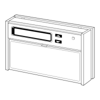
Illustrates the thermostat base with terminal designations and mounting details for reference.

Removing Old Thermostat

Mercury Handling Advisory

Advises on safe handling and disposal of mercury cells if the replaced unit contains them.

Wire Labeling and Disconnection

Emphasizes labeling wires before disconnecting and ensuring they do not fall back into the wall.

Mounting and Wiring

General Installation Warnings

Alerts users about voltage hazards, short-circuit risks, and NEC code compliance for installation.

Electric/Gas Jumper (Fan Option)

Details the W906 jumper setting for controlling the blower with auxiliary or emergency heat systems.

Temperature Unit Selection (°F or °C)

Instructions for changing the temperature display unit from Fahrenheit to Celsius by clipping W904.

Cycle Rate Selection (Fast or Slow)

Guides on selecting fast or slow cycle rates using the W905 jumper for temperature control.

O/B Terminal Switch Configuration

Explains how to set the O/B switch for heat pump changeover relay energization in COOL or HEAT.

Battery Location and Purpose

Informs about the location and function of the 2 'AAA' batteries for memory retention during power loss.

Attaching Thermostat Base to Wall

Provides steps for securely attaching the thermostat base to the wall using mounting screws and anchors.

Wire Routing and Connection

Details connecting wires to terminal screws and routing them carefully to prevent shorts.

Check Thermostat Operation

General Testing Static Discharge Note

Advises touching the thermostat casing to discharge static before interacting with controls.

Fan Operation Test

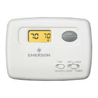
Steps to test the fan operation by switching the fan control to ON and AUTO positions.

Compressor Operation Caution

Warns against running the compressor without adequate oil heater operation or system readiness.

Heating System Operation Test

Procedure for testing heating operation in HEAT and EMER modes, including auxiliary heat activation.

Cooling System Operation Test

Steps to test cooling operation by setting the system to COOL and adjusting temperature settings.

Thermostat Buttons and Switches Identification

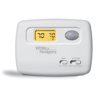
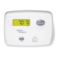
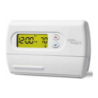
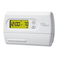
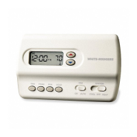
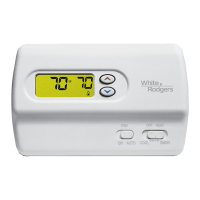
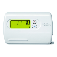
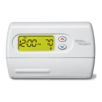
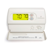
Identifies and explains the function of the thermostat's up/down arrows, FAN, and SYSTEM switches.

Thermostat Display Indicators Explained

Describes the meaning of various icons like Flame, Snowflake, EMER, and BATT on the thermostat display.

Configuration Menu

Entering the Configuration Menu

Instructions on how to enter the configuration menu by holding specific buttons while the system is OFF.

Second Stage Heat Operation

Explains the conditions for second stage heat activation based on temperature difference and FA setting.

Compressor Lockout Setting

Details the Compressor Lockout feature (CL ON/OFF) to protect the compressor from rapid cycling.

Temperature Display Adjustment

Allows adjustment of the displayed room temperature up to +/- 3 degrees to match user preference.

Backlit Display Option

Option to enable or disable the display backlight for improved visibility in low light conditions.

Troubleshooting Common Issues

Reset Operation Procedure

Procedure for resetting the thermostat by pressing buttons simultaneously to resolve display or erratic operation issues.

Battery Replacement Recommendation

Recommends replacing batteries annually for optimal performance, especially when the 'BATT' indicator appears.

No Heat/No Cool/No Fan Troubleshooting

Addresses common problems like no heating, cooling, or fan operation, listing possible causes and corrective actions.

Constant Operation Troubleshooting

Diagnoses issues where heating, cooling, or fan modes run continuously, suggesting wiring checks and system service.

Cycle Rate Adjustment

Explains how thermostat location, system size, or jumper settings influence cycle rate and how to adjust it.

Display Accuracy Adjustment

Guides on adjusting the thermostat's thermometer reading by +/- 3 degrees for accuracy.

Blank Display or Unresponsive Keypad

Provides solutions for blank displays or unresponsive keypads, typically involving voltage spikes or static discharge.

Related product manuals