Page 12
2019
WHYTE Service Manual
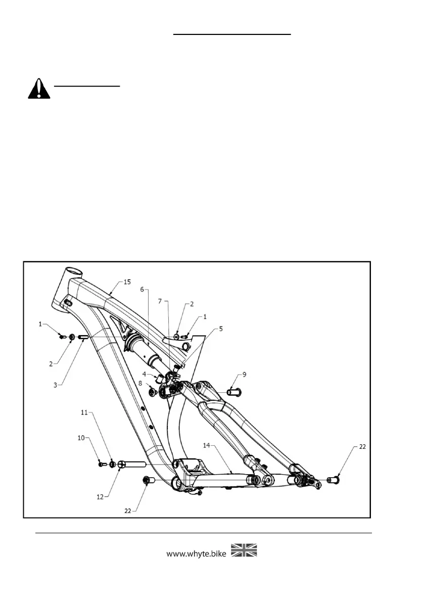
Figure 3: Disassembly of the
Rear Suspension (First Stage)
6.1.1 To remove only the rear Shock (6) from the frameset
IMPORTANT: When removing Rear Shock and/or Seat & Chain stays al-
ways brace the rear end and Shock to prevent damage to frame when
weight is removed.
Whilst referencing figure 3, using the T-25 Torx® Keys, undo the two M5 x 16mm
long Socket-head Capscrews (1) from the Ø8mm x 31mm long Hollow Pivot Pin (3)
that passes through the Main Frame (15) and front of the Rear Shock (6). Which-
ever Capscrew (1) becomes undone first, remove it and the adjacent Collar (2),
and pull the Pivot Pin (3) all the way out from the other side.
Using the 6mm Hex Key and the 8mm Hex Key, undo and remove both the
Flanged Nut M12 x 19mm long (4) from the Flanged Screw M12 x 15mm long (5),
that pass through the Shock Extender (7) and the rear of the Rear Shock (6). You
can now remove the Rear Shock (6).