Operating instruction (translation from original)
SVM 4001K-A / 4001K-C
Standstill monitoring for 1- and 3-phases motor without sensor system
Wieland Electric GmbH
Brennerstraße 10
– 14
+49 951 9324-0
+49 951 9324-198
-electric.com
Doc. # BA000926 – 06/2022 (Rev. E) SVM 4001K-A / 4001K-C 6 EN
3 Connection diagrams
Delta-connection
3-phases motor
Star connection
3-phases motor
Star delta-connection
3-phases moto
connection
1-phases motor
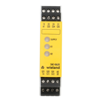
4 Display
After the connection of the power supply to the terminals A1 and A2 an internal test is
started. During this test the output contacts are open and the LED OK is illuminated red
(picture 2a).
The unit is ready after a faultless test displayed via the green illuminated LED OK (picture 2b).
5 Monitored function
A standstill is detected by evaluating the induced voltage (EMF) on a decelerating motor. The
output contacts open immediately if the EMF voltage exceeds the voltage set on the device.
The STOP LED goes out (Figure 2c).
When the set voltage is not reached, the configurable On delay is active. The STOP LED
flashes green (Figure 2d).
At the end of the delay time, the output contacts close. The STOP LED lights up green
(Figure 2b). The mechanical blockade of the motor is not being monitored.
6 Function of the control inputs I11 und I22
The standstill monitor is inactive when I11 and I22 are connected with 24 V DC. See table 1.
The standstill monitor is only active in FA1. The protective equipment is unlocked during a
standstill.
Table 1: Selecting the mode
Output contacts are only closed during standstill.
Output contacts are closed also during movement.
7 Switching value adjusting
• Connect the device to the operating voltage.
• Hold the SET key for approx. 3 s until all LEDs flash red.
• After pressing the key, the LEDs flash red according to the binary combination of the
current parameter level (see table 2).
• Briefly pressing the SET key assigns the next level in the sequence.
• Pressing the SET key for approx. 2 s permanently saves the new value and exits setting
mode.
For applications with synchronous motors, the switching threshold may only be adjusted
within a range of 1 … 7. If set within a range of 8 … 15, the motor standstill can be
adjustment
8 Setting the on delay time for output contacts
• Connect the device to the operating voltage.
• Hold the SET key for approx. 6 s until all LEDs flash green.
• After pressing the key, the LEDs flash according to the binary combination of the current
parameter level (see table 3). Every short press increases the value by one level.
• Pressing the key for approx. 2 s saves the new value.
• Pressing the key for ≥ 20 s ends the setting mode and restores the previous values.
Parameters cannot be changed while a fault is present, e.g. wire breakage or disconnected
motor!

 Loading...