Operating instruction (translation from original)
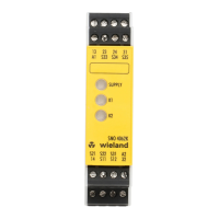
SVM 4001K-A / 4001K-C
Standstill monitoring for 1- and 3-phases motor without sensor system
Wieland Electric GmbH
Brennerstraße 10
– 14
+49 951 9324-0
+49 951 9324-198
-electric.com
Doc. # BA000926 – 06/2022 (Rev. E) SVM 4001K-A / 4001K-C 7 EN
9 Safety function during the adjustment
• In active setting mode, the safety functions and fault monitor are active.
• If the operating voltage is interrupted during setting mode or no keys are pressed for ≥ 20 s,
setting mode is ended without saving the new values.
• The previous parameters remain effective.
• New parameters must be saved to become effective.
• While the standstill monitor is in operation, it
continuously monitors for internal and external
faults. LED b8 flashes red (picture 4) if:
‒ Wire breakage in the measurement circuit.
‒ Inconsistent signals at the single phases
‒ Not allowed connection of the control inputs
I11/I22
‒ Power supply out of the tolerance range
‒ Internal unit faults
• The fault monitor is always active.
• In the event of a fault, the output contacts are
switched off.
After an external fault is corrected,
normal operation resumes.
If there were internal faults the unit
has to be returned to the
Table 4: Flashing sequence
9.1 Monitoring the protective equipment
In order to monitor the protective equipment, inputs I11 and I22 are disconnected.
Accordingly, the standstill monitor is constantly active.
-14/ 23-24 (serial circuit) are used to control the interlock of the protective
equipment. The contacts only close when the system drive is at a standstill. Then, the
protective equipment is unlocked.
process unit
safety cover
cover open/ closed
drive
EMF-Sensor wire
safety cover switch
10. safety cover enabling
9.2 Standstill monitoring
Operating mode FA2
In order to monitor the standstill, inputs I11 and I2 are controlled with 24V DC using the
switch of the protective equipment.
(protective equipment closed), the monitor is inactive.
-14 and 23-24 are permanently closed and the STOP LED lights up green.
Opening the protective hood initiates a change to FA1 mode.
Movement of the drive triggers the emergency stop function.
10 Technical data
24 V DC –15 +10 % reverse polarity protection
Current consumption at 24 V DC
Input voltage to L1, L2, L3
Current consumption L1, L2, L3
0.35 mA AC at 690 V AC / 5 kHz
Power consumption to A1/A2
Overvoltage and reverse polarity protection
operating voltage VCC
Maximum contact switching current
Minimum contact switching current
switching cycles
AC1: 230 V / 8 A, 100 000
DC1: 24 V / 8 A, 100 000
AC15: 230 V/3 A,
DC13: 24 V / 4 A
Mechanical life switching cycles
360 cycles/h at AC15/DC13
200 A/ mini circuit breaker B6 pre-fuse / 800 A/ 6 A
gL fuse gG
Response time, release time
-20 … +55°C, DIN IEC 60068-2-3
-40 … +70°C, DIN IEC 60068-2-3
Vibration resistance 3 axis
Sinus 10 … 55 Hz, 0.35 mm
10 cycles, 1 octave / min
Air and creep age distance
DIN EN 50178, safe isolation
Degree of protection / installation
position
IP20 housing / operator definable
Environment / overvoltage category
Single-core or finely stranded
1 × 0.2 … 2.5 mm²
2 × 0.2 … 1.0 mm²
Finely stranded with wire-end ferrule
according to DIN 46228
1 × 0.25 … 2.5 mm²
2 × 0.25 … 1.0 mm²
Maximum tightening torque
0.5 … 0.6 Nm
(5 … 7 lbf-in)
11 Principle shutdown
The user must set the switching threshold (EMF limit) and the ON delay time (T) to ensure
that the relays K1 and K2 switch only at the standstill of the motor.

 Loading...