EN
40202780.03 07/2017 EN/DE
32 WIKA operating instructions model A2G-50
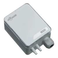
Dierential pressure transmitter, model A2G-50
Variant 1 Variant 2 Variant 3
Process connection Connecting nozzle (ABS), lower mount, for hoses with
inner diameter 4 or 6 mm
Power supply U
B
AC 24 V or DC 24 V ±10 %
Electrical connection Cable gland M16
Screw terminals
max. 1.5 mm
2
Output signal DC 0 … 10 V, 3-wire, 4 … 20 mA, 3-wire
Current consumption < 1.0 W (0 … 10 V), < 1.2 W (4 … 20 mA),
< 1.3 W (Modbus
®
)
Case Plastic (ABS)
Permissible medium
temperature
-10 … +50 °C
Ingress protection IP54
Weight 150 g
Modbus
®
version (option)
Modbus
®
communication
Protocol Modbus
®
via serial interface
Transfer mode RTU
Interface RS-485
Byte format (11 bits) in RTU mode
Coding system: 8 bits binary
Bits per byte:
- 1 Start bit
- 8 data bits, lowest-order bit is sent rst
- 1 bit for parity
- 1 stop bit
Baud rate 9,600, 19,200, 38,400 - adjustable in the conguration
Modbus
®
addresses 1 ... 247 addresses - adjustable in the conguration
For further specications see WIKA data sheet PE 88.02 and the order
documentation.
9. Specications

 Loading...