EN
40202780.03 07/2017 EN/DE
16 WIKA operating instructions model A2G-50
5. Commissioning, operation
5.2 Electrical mounting
The instrument is designed to operate with safety extra-low voltage
(SELV). As a rule, operate the dierential pressure transmitter in the
middle of the measuring range, since deviations can occur at the range
limits.
Operate the A2G-50 with a constant operating voltage (±0.2 V) and
ambient temperature. Prevent current/voltage spikes from switching the
power supply on or o.
For CE conformity, a properly grounded protective cable is required.
1. Unscrew the strain relief and feed the cable(s) through.
2. Connect the wires (see “Connection diagram”).
3. Tighten down the strain relief.
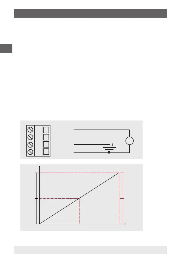
Connection diagram
■
Output signal DC 0 ... 10 V
V
Pressure P Signal [U]
100 % 10.0 V
50 % 5.0 V
0 % 0.0 V
Pressure P Signal [I]
100 % 20.0 mA
50 % 12.0 mA
0 % 4.0 mA
Time axis t [s]
0 ... 10 V
not connected
24 V
GND
Power supply
AC/DC 24 V
 Loading...