Do you have a question about the WIKA S-20 and is the answer not in the manual?
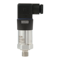
Provides general information about the pressure transmitter's design and manufacturing.
Explains warning, caution, and information symbols used in the manual.
Lists abbreviations used in the manual, such as 2-wire, 3-wire, UB, OV, S+.
Covers general safety precautions before installation, commissioning, and operation.
Defines the pressure transmitter's intended purpose and any limitations.
Specifies requirements for skilled personnel to operate the instrument safely.
Details hazards associated with hazardous media and residual media.
Explains the product label, including model, measuring range, and safety marks like CE.
Provides an overview of the technical specifications for the pressure transmitter.
Details permissible temperature ranges for medium and ambient conditions.
Specifies maximum permissible temperatures for various electrical connectors.
Outlines climate class requirements for storage, transport, and operation.
Defines vibration and shock resistance levels according to IEC standards.
Details results of free-fall tests for different packaging types.
Explains overpressure limits based on measuring range and process connections.
Lists maximum overpressure limits for various process connection types.
Details ingress protection ratings (IP) for different electrical connections.
Lists electrical protective measures like short-circuit resistance and overvoltage protection.
Specifies conformity with EMC and Pressure Equipment Directives.
Explains how the pressure transmitter measures pressure and converts it into an electrical signal.
Instructs users to cross-check the scope of delivery with the delivery note.
Advises checking for damage during transportation.
Recommends keeping original packaging for protection.
Details permissible storage conditions and factors to avoid.
Provides guidance on mechanical mounting and using original accessories.
Explains how to correctly seal process connections with parallel and tapered threads.
Details how to install the instrument, including using spanner flats and handling cooling elements.
Covers electrical mounting, cable assembly, and connector specifications.
Provides instructions for connecting cables, grounding shields, and ensuring tight seals.
Shows pin assignments for various electrical connectors (M12, Heavy-duty).
Details pin assignment for cable outlets using US code.
Shows pin assignment for field case connectors.
Lists pin assignments for cable outlets with moulded cables.
Provides pin assignment for 6-pin bayonet connectors.
Shows pin assignment for angular connector DIN 175301-803 A and C.
Explains how to set up the voltage supply, including energy limitation requirements.
Lists permissible power supply ranges for different output signals.
Details dissipation loss values and current/voltage supply limits.
Illustrates the procedure for adjusting the zero point of the pressure transmitter.
States that the pressure transmitter is maintenance-free and repairs are manufacturer-only.
Provides safety instructions for cleaning the instrument.
Mentions recalibration requirements, especially for hydrogen applications.
Lists common faults, their causes, and recommended measures for resolution.
Provides safety warnings and instructions for dismounting the instrument.
Gives instructions and warnings for returning the instrument.
Advises on environmentally compatible disposal of the instrument and packaging.
German version of the EC Declaration of Conformity.
English version of the EC Declaration of Conformity.
French version of the EC Declaration of Conformity.
Spanish version of the EC Declaration of Conformity.
| Accuracy | ≤ 0.5 % of span |
|---|---|
| Output Signal | 4 ... 20 mA, 0 ... 10 V, 0.5 ... 4.5 V ratiometric |
| Process Connection | G ¼ NPT, ¼ NPT |
| Electrical Connection | M12 x 1 |
| Materials (wetted) | Stainless steel |
| Temperature Range | -40 ... +125 °C |
| Ingress Protection | IP65 |
| Power Supply | 10 ... 30 V DC |