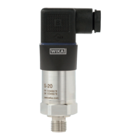
12 WIKA operating instructions pressure transmitter, model S-20
14043170.01 04/2013 GB/D/F/E
GB
3. Specications
Ingress protection
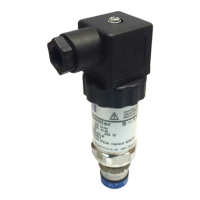
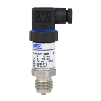
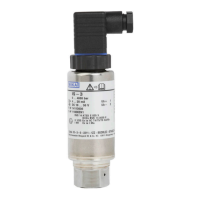
Electrical connection Ingress protection
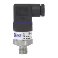
Angular connector DIN 175301-803 A IP 65
Angular connector DIN 175301-803 C IP 65
Circular connector M12 x 1 (4-pin) IP 67
Circular connector M12 x 1 (4-pin, metallic) IP 67
Bayonet connector (6-pin) IP 67
Field case IP 6K9K
Heavy-duty connector IP 68
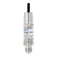
Cable outlet IP 67 IP 67
Cable outlet ½ NPT conduit IP 67
Cable outlet IP 68 IP 68
Cable outlet IP 68, FEP IP 68
Cable outlet IP 6K9K IP 6K9K
Electrical protective measures
The electrical protective measures are not valid for ratiometric output signals.
■
Short-circuit resistance: S
+
vs. U
-
■
Reverse polarity protection: U
+
vs. U
-
■
Resistance to overvoltage: DC 40 V (cULus: DC 35 V)
■
Insulation voltage: DC 750 V, not suitable as electric shock protection
CE conformity
■
EMC directive: 2004/108/EC, EN 61326 emission (group 1, class B) and interference immunity
(industrial application)
■
Pressure equipment directive: 97/23/EC
EM eld
30 V/m (80 ... 1,000 MHz)
RoHS conformity
RoHS-compliant
 Loading...